Table of Contents
Advertisement
Advertisement
Table of Contents

Related Manuals for LEYBOLD Sogevac Neo D Series


Summary of Contents for LEYBOLD Sogevac Neo D Series
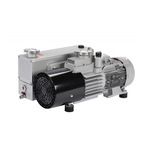
- Page 1 ® Sogevac Neo D NEO D 16 NEO D 25 NEO D 40 NEO D 65 Oil sealed rotary vane pump. Original Instruction manual 970100V to 970102V 970200V to 970202V 970300V to 970302V 970400V to 970402V And their variants. Document Y26/ SV Neo D 16 –...
-
Page 2: Table Of Contents
Operation Shutdown Ultimate pump pressure Taking out of use Maintenance Safety Information Maintenance Intervals Service at Leybold facilities Maintenance Work Troubleshooting Spare parts EC Conformance Declaration Declaration of Contamination of Compressors Vacuum Pumps and Components SV Neo D 16 – 25 - 40 – 65 Jan. -
Page 3: Important Safety Information
Always operate the pump with a properly connected protective earth con- ductor and make sure that the motor & FC connection box are closed. Use only the Leybold frequency converter for the pumps equipped with one. Lay the connecting lines so that these cannot be damaged. Protect the lines against humidity and contact with fluids. - Page 4 Liquid and solid particles or dust must not enter into the pump. Install the adequate filters, separators and/or condensers. In case of doubt consult Leybold. The intake line of the pump must never be connected to a device with over atmospheric pressure.
- Page 5 tive goggles also for protection against the oil. Some pumps use perfluoropolyether (PFPE) as lubricant. When handling PFPE you should observe the following: During thermal decomposition at temperatures over 290 °C toxic and corrosive gases are released. This is not likely to happen in a Sogevac pump.
-
Page 6: Description
Description 1. Description ® SOGEVAC pumps are designed for pumping of inert gases in the range of medium vacuum, between atmospheric pressure and end pressure of the pump. When removing condensable vapors, a gas ballast valve must be installed or opened. 1.1 Principle of operation ®... - Page 7 Description Unintentional venting of the vacuum chamber as well as oil suck back when Warning shutting down the pump are prevented by the integrated anti suck back valve. This valve is not a safety device and its correct operation & tightness can only be assured if the valve plate &...
-
Page 8: Technical Characteristics
Description 1.2 Technical characteristics Sogevac NEO D 16 NEO D 16 50 Hz 60 Hz Nominal speed m3. h Pumping speed m3. h Ultimate partial pressure mbar ≤ 8 x 10 ≤ 8 x 10 without gas ballast Ultimate total pressure with mbar ≤... - Page 9 Description 1.2 Technical characteristics Sogevac NEO D 25 NEO D 25 50 Hz 60 Hz Nominal speed m3. h Pumping speed m3. h Ultimate partial pressure mbar ≤ 8 x 10 ≤ 8 x 10 without gas ballast Ultimate total pressure with mbar ≤...
- Page 10 Description 1.2 Technical characteristics Sogevac NEO D 40 NEO D 40 50 Hz 60 Hz Nominal speed m3. h Pumping speed m3. h Ultimate partial pressure mbar ≤ 8 x 10 ≤ 8 x 10 without gas ballast Ultimate total pressure with mbar ≤...
- Page 11 Description 1.2 Technical characteristics Sogevac NEO D 65 NEO D 65 50 Hz 60 Hz Nominal speed m3. h Pumping speed m3. h Ultimate partial pressure mbar ≤ 8 x 10 ≤ 8 x 10 without gas ballast Ultimate total pressure with mbar ≤...
- Page 12 Description Dimensional drawing NEO D 16 Fig 1.1 SV Neo D 16 – 25 - 40 – 65 Jan. 2018 12 / 51...
- Page 13 Description Dimensional drawing NEO D 25 Fig 1.2 SV Neo D 16 – 25 - 40 – 65 Jan. 2018 13 / 51...
- Page 14 Description Installation drawing NEO D 25 Fig 1.2 SV Neo D 16 – 25 - 40 – 65 Jan. 2018 14 / 51...
- Page 15 Description Dimensional drawing NEO D 40 Fig 1.3 SV Neo D 16 – 25 - 40 – 65 Jan. 2018 15 / 51...
- Page 16 Description Dimensional drawing NEO D 65 Fig 1.4 SV Neo D 16 – 25 - 40 – 65 Jan. 2018 16 / 51...
- Page 17 Description NEO D 16 Pumping speed curve 50 Hz NEO D 16 Pumping speed curve 60 Hz SV Neo D 16 – 25 - 40 – 65 Jan. 2018 17 / 51...
- Page 18 Description NEO D 25 Pumping speed curve 50 Hz NEO D 25 Pumping speed curve 60 Hz SV Neo D 16 – 25 - 40 – 65 Jan. 2018 18 / 51...
- Page 19 Description NEO D 40 Pumping speed curve 50 Hz NEO D 40 Pumping speed curve 60 Hz SV Neo D 16 – 25 - 40 – 65 Jan. 2018 19 / 51...
- Page 20 Description NEO D 65 Pumping speed curve 50 Hz NEO D 65 Pumping speed curve 60 Hz SV Neo D 16 – 25 - 40 – 65 Jan. 2018 20 / 51...
-
Page 21: Ordering Information
Description 1.3 Ordering Information Exhaust Oil filter Inlet Mains socket Pump flange Filtre flange type Pompe Motor Huile Bride huile Bride aspi Prise alim Pumpe Öl refoul switch Ölfilter Einlass Leistungsstecker Auslass 970100V NEO D 16 LVO 700 25 KF 25 KF 970101V NEO D 16... -
Page 22: Accessories
Ordering information 1.4 Accessories Description Part-Nr. 1 Oil level switch 9700LS 2 Exhaust filter pressure switch 971471210 3 Exhaust filter pressure manometer 95193 4 Temperature switch 5 PT100 on 40 & 65 sizes only 971444320 P/N / Ref / Kat-Nr Plug pump side Plug supply side Length m... -
Page 23: Spare Parts
Oil filter Maintenance kit Repair kit 1.6 Lubricants Only original Leybold oil are to be used in the pumps, at least during their Warning warranty period. Following oil types can be used depending of the pump P/N, see § 1.3 Ordering Information ... -
Page 24: Transport And Storing
Transport and Storing 2 Transport and Storing 2.1 Transport and packaging ® SOGEVAC vacuum pumps pass a rigorous operating test in our factory and are packaged to avoid transport damages. Please check packaging on delivery for transport damages. The outer package can bear a shock indicator, turning red at 50 g. - Page 25 Transport and Storing Pump fixation The pumps are bolted by screws. Screws are to be removed from under the pallet using a 13 mm wrench. Pump lifting The pump is then ready to be shifted or lifted off the pallet. Due to the pump weight ONLY a suitable lifting device shall be used to lift the pump at the lifting lug (CE regulations) A lifting device is the only officially recommended way of handling the pump.
-
Page 26: Mounting Orientation
We recommend that you contact the service from Leybold. SV Neo D 16 – 25 - 40 – 65 Jan. 2018... -
Page 27: Installation
Installation 3 Installation It is essential to observe the following instructions step by step to ensure safe Warning start-up. Before installing the pump you must reliably disconnect it from the electrical power supply and prevent the pump form running up inadvertently. Observe all safety regulations. -
Page 28: Connection To System
Installation 3.2 Connection to the system Caution Intake Side ■ Pump should be connected to inlet line without any tension. Use flex lines or pipe unions in your inlet and exhaust lines so that they can be easily removed for pump maintenance. ■... -
Page 29: Electrical Connections
Installation 3.3 Electrical connections Ensure that incoming power to the pump is off before wiring the motor or Warning altering the wiring. The specific wiring and instructions for installation given in the manual for the electric motor must be followed. The pump shall be adequately earthed to prevent the accumulation of static electricity. - Page 30 Installation 1 phase motors Should the pump be connected to a standard wall socket, it must be checked that a building protection rated 16 A is installed (fuse or breaker) to protect the power cable. Even if the pump is not operating, live voltage is present in the connection box ! Voltage and frequency mentioned on the pump nameplate must agree with the supply voltage.
- Page 31 Installation Temperature Switch (on given variants only) A temperature switch can be retrofitted on the pumps and is available as an accessory. It is a dry contact normally closed, tripping at 100 °C. Hysteresis approx... 20 °C The thermal switch can be connected in series with the motor protection relay. Switching ratings DC 3A/60V Max AC 5A/25V Max...
-
Page 32: Start-Up
Installation 3.4 Start-up Caution Control Parameters for the Ignition Prevention System Temperature Temperature Oil Casing Oil Level switch Sensor PT100 Pressure Switch Switch Alarm Value 95 °C Pump Stop 105 °C 105 °C At switching At switching Value and At switching Immediately After 20 s After 20 s... -
Page 33: Operation
Operation 4 Operation 4.1 Operation To avoid overloading the motor, do not start the pump more than six times Warning within one hour. If frequent starts are needed, the pump shall run continuously and be linked to the vacuum vessel by means of a valve. In that case, regulation will be made by the valve and not by start/stop of the pump. - Page 34 Operation When vapors are pumped, the pump must not be switched off immediately Caution after completion of the process because the condensate dissolved in the pump oil may cause changes or corrosion. To prevent this, the pump must continue to operate with open gas ballast valve and closed intake port until the oil is free of condensate.
-
Page 35: Shutdown
The best ultimate pressures can be obtained at a low pump temperature and by using the recommended oil types. 4.4 Taking out of use Please contact Leybold for all relation question about the disposal of spares, consumables or the entire pump SV Neo D 16 – 25 - 40 – 65 Jan. -
Page 36: Maintenance
Never mount used seals; always mount new seals. Only the use of genuine Leybold parts is allowed ! Any integration of non Leybold parts or non- authorized repairs will cancel the pump CE or ATEX certification and will waive all Leybold responsibilities. -
Page 37: Maintenance Intervals
Maintenance 5.2 Maintenance Intervals The intervals stated in the maintenance schedule are approximate values for Warning normal pump operation. Unfavorable ambient conditions and/or aggressive media may significantly reduce the maintenance intervals. Maintenance job Frequency Section Checking the oil level Daily. 5.4.A Checking the oil condition Depends of process, at least weekly. -
Page 38: Service At Leybold Facilities
In connection with this, you may be interested in the Leybold practical seminars, in which maintenance, repair and testing information for the ®... -
Page 39: Maintenance Work
Maintenance 5.4 Maintenance Work 5.4.A Checking the oil level The pump’s oil level during operation must always be between the middle and top edge of the oil-level glass. When necessary, switch off the pump and add the correct quantity of oil. Overfilling leads to oil losses at high intake pressures High oil consumption often indicates that exhaust filters are clogged (See 5.4.D). - Page 40 Maintenance 5.4.C Oil change Always change the oil when the pump is switched off but still at working Warning temperature. If there is a risk of the oil being polymerized by the connected process, change the oil immediately after operation of the pump. Pump in function is hot and some surfaces could reach a temperature higher than 80 °C (176 °F).
- Page 41 Maintenance 5.4.D Replacing the Exhaust Filters Tools required : - Allen key 6 mm. - Box wrench 10 mm. Warning oil filter key (710 73 532) Remove the 4 screws of the exhaust filter cover plate Pull out the exhaust filter ...
- Page 42 Maintenance 5.4.E Checking the float valve Tools required : Allen Key 6 mm If the pressure does not fall below approx. 5 mbar during pump operation, check the tightness of the float valve. Remove the exhaust filter with the exhaust flange. Remove the float valve screw and pull the float valve assembly out of the float chamber.
- Page 43 5.4.H Replacing the Pump Module Please consult Leybold 5.4.I Replacement of electrical motor Please consult Leybold for specific maintenance works to be carried e.g. bearing replacement. The motor can only be exchange with an identical one for the same manufacturer and marking.
-
Page 44: Troubleshooting
Trouble shooting 6 Trouble shooting SV Neo D 16 – 25 - 40 – 65 Jan. 2018 44 / 51... - Page 45 Trouble shooting * Reference section: This column refers to the section in the Operating Instructions that contains the applicable repair information. SV Neo D 16 – 25 - 40 – 65 Jan. 2018 45 / 51...
-
Page 46: Spare Parts
When ordering spare parts and accessories, always state pump type and serial number. You can find part numbers in the spare parts list. The pump loses its CE & ATEX certification if non genuine Leybold parts are used. ®... - Page 47 Spare parts SV Neo D 16 – 25 - 40 – 65 Jan. 2018 47 / 51...
-
Page 48: Ec Conformance Declaration
CE Declaration CE Declaration SV Neo D 16 – 25 - 40 – 65 Jan. 2018 48 / 51... -
Page 49: Declaration Of Contamination Of Compressors
Declaration of Contamination SV Neo D 16 – 25 - 40 – 65 Jan. 2018 49 / 51... - Page 50 Notes Notes SV Neo D 16 – 25 - 40 – 65 Jan. 2018 50 / 51...
- Page 51 SV Neo D 16 – 25 - 40 – 65 Jan. 2018 51 / 51...
Need help?
Do you have a question about the Sogevac Neo D Series and is the answer not in the manual?
Questions and answers