Table of Contents
Advertisement
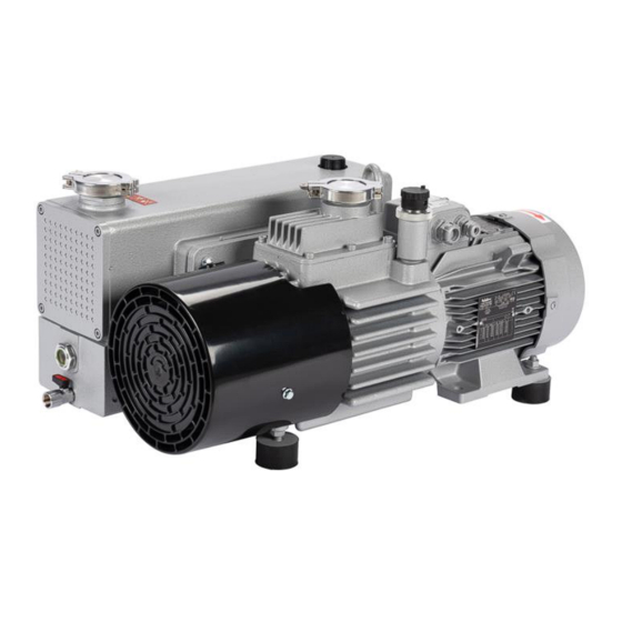
Sogevac Neo D
NEO D 16
NEO D 25
NEO D 40
NEO D 65
Oil sealed rotary vane pump.
Original Instruction manual
P/N
970100V to 970103V
970200V to 970202V
970300V to 970302V
970400V to 970402V
970102A33
970202A33
970302A33
970402A33
And their variants.
Document Y26/300731504/002/C4
SV Neo D 16 – 25 - 40 – 65
June 2021
1 / 62
Advertisement
Table of Contents

Related Manuals for LEYBOLD Sogevac Neo D 16


Summary of Contents for LEYBOLD Sogevac Neo D 16
- Page 1 Sogevac Neo D NEO D 16 NEO D 25 NEO D 40 NEO D 65 Oil sealed rotary vane pump. Original Instruction manual 970100V to 970103V 970200V to 970202V 970300V to 970302V 970400V to 970402V 970102A33 970202A33 970302A33 970402A33 And their variants. Document Y26/300731504/002/C4 SV Neo D 16 –...
-
Page 2: Table Of Contents
Operation Shutdown Ultimate pump pressure Taking out of use Maintenance Safety Information Maintenance Intervals Service at Leybold facilities Maintenance Work Troubleshooting Spare parts EC Conformance Declaration Declaration of Contamination of Compressors Vacuum Pumps and Components SV Neo D 16 – 25 - 40 – 65... -
Page 3: Important Safety Information
Operating Instructions. Note The Leybold SOGEVAC Neo D have been designed for safe and efficient operation when used properly and in accordance with these Operating Instructions. It is the responsibility of the user to carefully read and strictly observe all safety precautions described in this section and throughout the Operating Instructions. - Page 4 Liquid and solid particles or dust must not enter the pump. Install the adequate filters, separators and/or condensers. In case of doubt consult Leybold. The intake line of the pump must never be connected to a device with over atmospheric pressure. Design the exhaust line so that no pressure higher than 1,15 bar abs.
- Page 5 Important Safety Information Some pumps use perfluoropolyether (PFPE) as lubricant. When handling PFPE you should observe the following: During thermal decomposition at temperatures over 290 °C toxic and corrosive gases are released. This is not likely to happen in a Sogevac pump. When handling PFPE keep it way from open fires.
-
Page 6: Description
Description 1. Description SOGEVAC pumps are designed for pumping of inert gases in the range of medium vacuum, between atmospheric pressure and end pressure of the pump. When removing condensable vapors, a gas ballast valve must be installed or opened. 1.1 Principle of operation The SOGEVAC Neo D are oil-sealed rotary vane pumps. - Page 7 Description Unintentional venting of the vacuum chamber as well as oil suck back when Warning shutting down the pump are prevented by the integrated anti suck back valve. This valve is not a safety device and its correct operation & tightness can only be assured if the valve plate &...
- Page 8 Description Potential Ignition Sources An Ignition hazard assessment has been carried out according to the European Standard EN 13463-1. (EN 13463-1 Non-electrical equipment for potentially explosive atmospheres — Part 1: Basic method and requirements) This has identified that the following ignition sources may occur during operation of the pump: Potential Ignition Sources Comments...
- Page 9 CLC/TR 50404:2003 Electrostatics - Code of practice for the avoidance of hazards due to static electricity.) NOTE: Only original Leybold replacement exhaust gas filter cartridges and gas inlet filter cartridges should be used as these have a special construction to ensure earthing.
-
Page 10: Technical Characteristics
Description 1.2 Technical characteristics Sogevac NEO D 16 NEO D 16 50 Hz 60 Hz Nominal speed (cfm) 19 (11.2) 23 (13.5) Pumping speed (cfm) 16 (9.4) 19 (11.2) ≤ 8 x 10 Ultimate total pressure mbar (Torr) without gas ballast (≤... - Page 11 Description 1.2 Technical characteristics Sogevac NEO D 25 NEO D 25 50 Hz 60 Hz (cfm) Nominal speed (cfm) Pumping speed ≤ 8 x 10 Ultimate total pressure mbar (Torr) without gas ballast (≤ 6 x 10 ≤ 0.1 Ultimate total pressure with mbar (Torr) standard gas ballast (≤...
- Page 12 Description 1.2 Technical characteristics Sogevac NEO D 40 NEO D 40 50 Hz 60 Hz (cfm) Nominal speed (cfm) Pumping speed ≤ 8 x 10 Ultimate total pressure mbar (Torr) without gas ballast (≤ 6 x 10 ≤ 0.1 Ultimate total pressure with mbar (Torr) standard gas ballast (≤...
- Page 13 Description 1.2 Technical characteristics Sogevac NEO D 65 NEO D 65 50 Hz 60 Hz (cfm) Nominal speed (cfm) Pumping speed ≤ 8 x 10 Ultimate total pressure mbar (Torr) without gas ballast (≤ 6 x 10 ≤ 0.1 Ultimate total pressure with mbar (Torr) standard gas ballast (≤...
- Page 14 Description Dimensional drawing NEO D 16 Fig 1.1 SV Neo D 16 – 25 - 40 – 65 June 2021 14 / 62...
- Page 15 Description Dimensional drawing NEO D 25 Fig 1.2 SV Neo D 16 – 25 - 40 – 65 June 2021 15 / 62...
- Page 16 Description Installation drawing NEO D 16 & 25 Fig 1.3 SV Neo D 16 – 25 - 40 – 65 June 2021 16 / 62...
- Page 17 Description Dimensional drawing NEO D 40 Fig 1.4 SV Neo D 16 – 25 - 40 – 65 June 2021 17 / 62...
- Page 18 Description Dimensional drawing NEO D 65 Fig 1.5 SV Neo D 16 – 25 - 40 – 65 June 2021 18 / 62...
- Page 19 Installation drawing NEO D 40 Installation drawing NEO D 65 Fig 1.6 SV Neo D 16 – 25 - 40 – 65 June 2021 19 / 62...
- Page 20 Description NEO D 16 Pumping speed curve 50 Hz NEO D 16 Pumping speed curve 60 Hz SV Neo D 16 – 25 - 40 – 65 June 2021 20 / 62...
- Page 21 Description NEO D 25 Pumping speed curve 50 Hz NEO D 25 Pumping speed curve 60 Hz SV Neo D 16 – 25 - 40 – 65 June 2021 21 / 62...
- Page 22 Description NEO D 40 Pumping speed curve 50 Hz NEO D 40 Pumping speed curve 60 Hz SV Neo D 16 – 25 - 40 – 65 June 2021 22 / 62...
- Page 23 Description NEO D 65 Pumping speed curve 50 Hz NEO D 65 Pumping speed curve 60 Hz SV Neo D 16 – 25 - 40 – 65 June 2021 23 / 62...
-
Page 24: Ordering Information
Ordering Information 1.3 Ordering Information Exhaust Oil filter Inlet Mains socket Pump flange Filtre flange type Pompe Motor Huile Bride huile Bride aspi Prise alim Pumpe Öl refoul switch Ölfilter Einlass Leistungsstecker Auslass 970100V NEO D 16 LVO 700 25 KF 25 KF 970100V4100 NEO D 16 LVO 700... - Page 25 Ordering Information Exhaust Oil filter Inlet Mains socket Pump flange Filtre flange type Pompe Motor Huile Bride huile Bride aspi Prise alim Pumpe Öl refoul switch Ölfilter Einlass Leistungsstecker Auslass 970200V NEO D 25 LVO 700 25 KF 25 KF 970200V4100 NEO D 25 LVO 700 25 KF...
- Page 26 Ordering Information Exhaust Oil filter Inlet Mains socket Pump flange Filtre flange type Pompe Motor Huile Bride huile Bride aspi Prise alim Pumpe Öl refoul switch Ölfilter Einlass Leistungsstecker Auslass 970300V NEO D 40 LVO 700 40 KF 40 KF 970300V4200 NEO D 40 LVO 700 40 KF...
- Page 27 Ordering Information Exhaust Oil filter Inlet Mains socket Pump flange Filtre flange type Pompe Motor Huile Bride huile Bride aspi Prise alim Pumpe Öl refoul switch Ölfilter Einlass Leistungsstecker Auslass 970402V NEO D 65 LVO 700 40 KF 40 KF 970402V4100 NEO D 65 LVO 700 40 KF...
- Page 28 Ordering Information 1.3 Ordering Information ATEX Size Part-Nr. Inside Outside Inside Outside ATEX Marking temp. temp. gas group class class group Ex II (i) 3 G h IIC 160°C Gc (10 <Ta< SV Neo D 16 970102A33 160°C 40°C) X / (o) 3 G IIC T3 Gc (10 <Ta< 40°C) X Ex II (i) 3 G h IIC 160°C Gc (10 <Ta<...
- Page 29 Ordering Information NOTE. The Temperature Class and the actual maximum surface temperature of the equipment includes the safety margin to the minimum ignition temperature of the potentially explosive atmosphere as required in EN 1127-1 Allowable ambient temperature for use of the pump 10°C< Ta < 40°C Special operating conditions for safe use apply - see information given in this manual SV Neo D 16 –...
-
Page 30: Accessories
970RA02 D 40 Stability of pump is insured with accessories of Leybold; mounting of any other accessory will engage the responsibility of user concerning stability of pump. In case a direct Roots pump coupling is used, it is important to check the gas temperature due to the Roots compression. - Page 31 SV Neo D 40 & 65 need C19 cables The power cords are not included in the pump scope of delivery. We include a C14 resp. C20 plug. Should non Leybold power cords be used, take below minimum cross sections: Pump 115 V...
-
Page 32: Spare Parts
EK9702GEN EK9703GEN EK9704GEN Only original Leybold spare parts are to be used in the pumps. A non-respect of this will entail a loss of the pump’s ATEX certification. 1.6 Lubricants Only original Leybold oil are to be used in the pumps, at least during their Warning warranty period. -
Page 33: Transport And Storing
Transport and Storing 2 Transport and Storing 2.1 Transport and packaging SOGEVAC vacuum pumps pass a rigorous operating test in our factory and are packaged to avoid transport damages. Please check packaging on delivery for transport damages. Outer packaging is made by a wood pallet &... - Page 34 Transport and Storing Pump fixation The pumps are bolted by screws. Screws are to be removed from under the pallet using a 13 mm wrench. Pump lifting The pump is then ready to be shifted or lifted off the pallet. Due to the pump weight ONLY a suitable lifting device shall be used to lift the pump at the lifting lug (CE regulations) A lifting device is the only officially recommended way of handling the pump.
-
Page 35: Mounting Orientation
If the pump has been shelved for over one-year, standard maintenance must be done, and the oil must be exchanged too before the pump is put into service once more. We recommend that you contact the service from Leybold. SV Neo D 16 – 25 - 40 – 65 June 2021... -
Page 36: Installation
Installation 3 Installation It is essential to observe the following instructions step by step to ensure safe Warning start-up. Before installing the pump, you must reliably disconnect it from the electrical power supply and prevent the pump form running up inadvertently. Observe all safety regulations. -
Page 37: Connection To System
Installation 3.2 Connection to the system Intake Side Caution ■ Pump should be connected to inlet line without any tension. Use flex lines or pipe unions in your inlet and exhaust lines so that they can be easily removed for pump maintenance. ■... -
Page 38: Electrical Connections
Installation 3.3 Electrical connections Ensure that incoming power to the pump is off before wiring the motor or Warning altering the wiring. The specific wiring and instructions for installation given in the manual for the electric motor must be followed. The pump shall be adequately earthed to prevent the accumulation of static electricity. - Page 39 Installation The pump is designed for direct starting even under load conditions, i.e. the pump can be switched on against vacuum in the intake port. After connecting the motor and after every time you alter the wiring, check the direction of rotation. Refer to the arrow marked on the generator fan cover center and on the motor cover: During the check, the intake port should be open.
- Page 40 Installation Frequency converter Should the pump be connected to a standard wall socket, it must be checked that a building protection rated 16 A is installed (fuse or breaker) to protect the power cable. The frequency converter itself is self-protecting. Voltage and frequency mentioned on the pump nameplate must agree with the supply voltage.
- Page 41 Installation Oil level Switch (on given variants only) An oil level switch can be retrofitted on the pumps and is available as an accessory. The pump must be switched off and the pump and oil level checked immediately if the oil level is too low.
-
Page 42: Start-Up
Installation 3.4 Start-up Control Parameters for the Ignition Prevention System (ATEX variants) Caution Option Temperature Temperature Oil Casing Oil Level switch Sensor PT100 Pressure Switch Switch Alarm Value 90 °C Pump Stop 100 °C 100 °C At switching At switching Value and At switching Immediately... -
Page 43: Operation
Operation 4 Operation 4.1 Operation To avoid overloading the motor, do not start the pump more than six times Warning within one hour. If frequent starts are needed, the pump shall run continuously and be linked to the vacuum vessel by means of a valve. In that case, regulation will be made by the valve and not by start/stop of the pump. - Page 44 Operation When vapors are pumped, the pump must not be switched off immediately Caution after completion of the process because the condensate dissolved in the pump oil may cause changes or corrosion. To prevent this, the pump must continue to operate with open gas ballast valve and closed intake port until the oil is free of condensate.
-
Page 45: Shutdown
The best ultimate pressures can be obtained at a low pump temperature and by using the recommended oil types. 4.4 Taking out of use Please contact Leybold for all relation question about the disposal of spares, consumables or the entire pump SV Neo D 16 – 25 - 40 – 65... -
Page 46: Maintenance
CE compliance or ATEX ratings and may cause problems when filing warranty claims or free Leybold from any responsibility. All work must be done by suitably trained ATEX personnel on ATEX pumps. Before any... -
Page 47: Maintenance Intervals
Maintenance 5.2 Maintenance Intervals The intervals stated in the maintenance schedule are approximate values for Warning normal pump operation. Unfavorable ambient conditions and/or aggressive media may significantly reduce the maintenance intervals. Maintenance job non Frequency Section ATEX pumps Checking the oil level Daily. -
Page 48: Service At Leybold Facilities
In connection with this, you may be interested in the Leybold practical seminars, in which maintenance, repair and testing information for the Sogevac pumps is conveyed by qualified trainers. -
Page 49: Maintenance Work
Maintenance 5.4 Maintenance Work 5.4.A Checking the oil level The pump’s oil level during operation must always be in the upper quarter of the oil-level glass. When necessary, switch off the pump and add the correct quantity of oil. Overfilling leads to oil losses at high intake pressures. High oil consumption often indicates that exhaust filters are clogged (See 5.4.D). - Page 50 Maintenance 5.4.C Oil change Always change the oil when the pump is switched off but still at working Warning temperature. If there is a risk of the oil being polymerized by the connected process, change the oil immediately after operation of the pump. Pump in function is hot and some surfaces could reach a temperature higher than 80 °C (176 °F).
- Page 51 Maintenance 5.4.D Replacing the Exhaust Filters Tools required: - Allen key 6 mm. - Box wrench 10 mm. Warning oil filter key (710 73 532) • Remove the 4 screws of the exhaust filter cover plate • Pull out the exhaust filter •...
- Page 52 Maintenance 5.4.E Checking the float valve Tools required: Allen Key 6 mm If the pressure does not fall below approx. 5 mbar during pump operation, check the tightness of the float valve. Remove the exhaust filter with the exhaust flange. Remove the float valve screw and pull the float valve assembly out of the float chamber.
- Page 53 5.4.H Replacing the Pump Module Please consult Leybold 5.4.I Replacement of electrical motor Please consult Leybold for specific maintenance works to be carried e.g. bearing replacement. The motor can only be exchange with an identical one for the same manufacturer and marking.
-
Page 54: Troubleshooting
Trouble shooting 6 Trouble shooting SV Neo D 16 – 25 - 40 – 65 June 2021 54 / 62... - Page 55 Trouble shooting * Reference section: This column refers to the section in the Operating Instructions that contains the applicable repair information. SV Neo D 16 – 25 - 40 – 65 June 2021 55 / 62...
- Page 56 Consumables and main spare parts kits for SOGEVAC pumps are usually available on stock at Leybold service centers. The list of these parts is given here after and in the spare parts table where the contents of each kits is detailed.
-
Page 57: Spare Parts
Spare parts Spare parts Are in a separate document SV Neo D 16 – 25 - 40 – 65 June 2021 57 / 62... - Page 58 EU Declaration SV Neo D 16 – 25 - 40 – 65 June 2021 58 / 62...
- Page 59 China RoHS Declaration Materials Declaration 材料声明 In accordance with the requirements of the Chinese regulatory requirement on the Management Methods for the Restriction of the Use of Hazardous Substances in Electrical and Electronic Products Order No. 32 (also known as ‘China RoHS 2.0’) and SJ/T 11364 Marking for the Restricted Use of Hazardous Substances in Electronic and Electrical Products: 依照中国对电子电器产品有害物质限制使用管理办法的法律法规要求...
- Page 60 Declaration of Contamination SV Neo D 16 – 25 - 40 – 65 June 2021 60 / 62...
- Page 61 Notes Notes SV Neo D 16 – 25 - 40 – 65 June 2021 61 / 62...
- Page 62 SV Neo D 16 – 25 - 40 – 65 June 2021 62 / 62...
Need help?
Do you have a question about the Sogevac Neo D 16 and is the answer not in the manual?
Questions and answers