Table of Contents
Advertisement
Advertisement
Table of Contents

Related Manuals for LEYBOLD TRIVAC S 16 B


Summary of Contents for LEYBOLD TRIVAC S 16 B
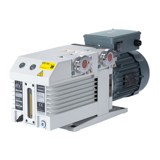
- Page 1 LEYBOLD VACUUM Vacuum Pumps Instrumentation Fittings and Valves GA 01.202/9.02 ® TRIVAC Rotary Vane Vacuum Pump S/D 16, 25 B Cat.-No. 102 65/66/75/76 103 25/26/27/28/31/32/35/36/37/38/48/49 112 65/66/75/76 113 25/26/27/28/29/31/32 113 35/36/37/38/39/48/49 113 33 Operating Instructions...
-
Page 2: Table Of Contents
Removing and Remounting the Pump Module20 Used oils coming from vacuum pumps must not be Service at Leybold’s ....20 mixed with other substances. -
Page 3: Description
Description Key to Fig. 1 1 Oil filter OF 4-25 2 Exhaust filter AF 16-25 3 Condensate trap AK 16-25 Fig. 1 TRIVAC-B with accessories 1 Description 1.1 Function The rotor (2/7), mounted eccentrically in the pump hou- TRIVAC-B pumps are oil-sealed rotary vane pumps. The sing (2/6), has two radially sliding vanes (2/5) which divi- TRIVAC S16 B and S 25 B are single-stage pumps, and de the pump chamber into several compartments. - Page 4 Description Key to Fig. 2 1 Intake port 2 Dirt trap 3 Anti-suckback valve 4 Intake channel 5 Vanes 6 Pump chamber 7 Rotor 8 Cover plate, connection for inert gas ballast 9 Exhaust channel 10 Exhaust valve 11 Internal demister 12 Spring buckles 13 Cover plate, connection for oil filter Fig.
-
Page 5: Supplied Equipment
Description Key to Fig. 3 1 Accessories 2 Bearings 3 Non-return valve 4 Pump chamber of the TRIVAC 5 Oil reservoir 6 Oil pump Fig. 3 Schematic of the lubricating system Key to Fig. 4 1 Oil reservoir 5 Valve seat 2 Spring 6 Valve disk 3 Control piston... -
Page 6: Accessories
Oil N 62 177 01 177 02 20 l 177 03 Arctic oil SHC 244 200 28 229 (order from Leybold Cologne, Germany) Anderol RCFE 96 N 200 39 839 Oil HE-200 1 qt 98 198 006 (order from 12 qt case 98 198 049 LHVP, Export Pa.,... -
Page 7: Technical Data
D25B D16B S25B S16B mbar Druck/Pressure/Pression with gas ballast without gas ballast Fig. 5 Pumping speed characteristics of the TRIVAC S 16 B to TRIVAC D 25 B, 50 Hz operation, SI units GA 01.202/9.02 - 03/96... - Page 8 Description GA 01.202/9.02 - 03/96...
-
Page 9: Operation
Operation Key to Fig. 7 1 Handle 2 Intake port 3 Exhaust port 4 Oil-level glass 5 Gas ballast knob 6 Threaded connection M 16 x 1.5 for inert gas ballast 7 Adapter 8 Cover plate 9 Cover plate; connection for oil filter Abb. -
Page 10: Electrical Connection
At 230 V use an at least a 6 A slow-blow or a 10 A fast- mend the installation of an additional blow fuse. exhaust filter (Leybold accessory). The direction of rotation need not be checked as it is fixed. -
Page 11: Start-Up
Operation Star connection Delta connection Fig. 8 Connection diagram for TRIVAC-B with 50 Hz 3-phase motor 2.3.2 Pump with Three-Phase AC Motor 2.4 Start-up TRIVAC-B pumps with a three-phase motor are supplied Each time before starting up ensure that the oil level is without accessories for electrical connection. - Page 12 Operation 2.4.1 Areas of Application Caution The pump is not suitable for pumping of: - ignitable and explosive gases or vapours - oxidants - pyrophorous gases. The pumps are not suitable for pumping of liquids or very dusty media. Suitable pro- tective devices must be installed.
-
Page 13: Operation
Operation 2.5 Operation Once all vapours have been pumped off from a process (e.g. during drying), the gas ballast valve can be closed to improve the attainable ultimate pressure. TRIVAC-B pumps can pump condensable gases and vapours, provided that the gas ballast valve (7/5) is open and the pump has attained its operating temperature. -
Page 14: Switching Off/Shutdown
Operation 2.6 Switching Off/Shutdown 2.6.1 Shut-Down through Monitoring Com- ponents Under normal circumstances, all that you need do is to electrically switch off the TRIVAC-B. When the pump has been switched off due Caution to overheating sensed by the motor coil pro- No further measures will be required. -
Page 15: Maintenance
The amount of oil required for an oil check should be drained via the oil-drain port (9/4) into a beaker or simi- If you send a pump to LEYBOLD for repair please indi- lar container with the pump switched off but still at ope- cate any harmful substances existing in or around the rating temperature. -
Page 16: Oil Change
Maintenance Key to Fig. 9 1 Oil-fill plug 2 Oil-level mark maximum 3 Oil-level mark minimum 4 Oil-drain plug Abb. 9 Oil change 3.2 Oil Change Screw the oil-drain plug back in (check the flat gasket and reinstall a new one if necessary). For proper operation of the pump, it is essential that the Remove the oil-fill plug (9/1) and fill in with fresh oil. -
Page 17: Cleaning The Dirt Trap
Maintenance Key to Fig. 10 1 Oil case 2 Spring buckles 3 Demister 4 Frame for demister 5 Hex. socket screws (5 pcs.) 6 Silencing nozzle 7 Gasket Fig. 10 Removal and fitting of the internal demister 3.3 Cleaning the Dirt Trap The resultant noise at high intake pressures indicates that the internal demister is dirty. -
Page 18: Disassembly And Reassembly Of The Electric
Maintenance Key to Fig. 11 1 Gasket 2 Handle 3 Hex. socket screw 4 Electric motor 5 Intermediate flange 6 Hex. socket screw 7 Coupling 8 Threaded pin Fig. 11 Disassembly and reassembly of the electric motor 3.5 Disassembly and Reas- Remove the handle (11/2). -
Page 19: Replacing The Outer Shaft Seal
Maintenance Key to Fig. 12 1 Coupling element 2 Hexagon socket screw 3 Spring washer 4 Coupling (one half) 5 Key 6 Bushing 7 O-ring 8 Shaft seal 9 Centering disk 10 Hexagon socket screws Position of the shaft seal Fig. -
Page 20: Removing And Remounting The Pump Module20
3.7.1 Removing the Pump Module 3.8 Service at Leybold’s Drain the oil and remove the oil case (see Section 3.4). If a pump is returned to Leybold, indicate whether the Unscrew the hex. nuts (13/1). pump free of substances damaging to health or whether it is contaminated. -
Page 21: Storing The Pump
When a pump is put into operation after it has been shel- ved for over one year, standard maintenance should be run on the pump and the oil should also be exchanged (see Operating Instructions). We recommend that you contact the Leybold service. GA 01.202/9.02 - 03/96... -
Page 22: Maintenance Plan
Maintenance 3.10 Maintenance Plan (Recommendation) Rotary vane pumps Measurement/test quantity Interval Remarks TRIVAC S/D 16 B Operating / auxiliary 6m a n-a VE VP Refer also to the Operating Instructions - Section: indivi- TRIVAC S/D 25 B materials dual components. Operate the pump for at least 0.8 Condensed water is thus removed from the oil. - Page 23 We recommend a twice yearly service on the pump covering the following: • Cleaning • Checking of the individual components • Exchange of all seals • Functional check. This check should be run by the Leybold service. GA 01.202/9.02 - 03/96...
-
Page 24: Troubleshooting
Troubleshooting 4 Troubleshooting Fault Possible cause Remedy Repair* Pump does not Wiring is malfunctioning. Check and repair wiring. start. Motor protection switch incorrectly set Set motor protection switch properly. (3-phase motors only). Operating voltage does not match motor. Replace the motor. Motor is malfunctioning. - Page 25 Declaration of Contamination of Vacuum Equipment and Components The repair and/or service of vacuum equipment and components will only be carried out if a correctly completed declaration has been submitted. Non-completion will result in delay. The manufacturer could refuse to accept any equipment without a declara- tion.
-
Page 26: Ec Declaration Of Conformity
EC Declaration of Conformity We - LEYBOLD Vakuum GmbH - herewith declare that The products conform to the following directives: the products defined below meet the basic requirements • EC Directive on Machinery (89/392/EEC) and subse- regarding safety and health of the relevant EEC direc-... - Page 27 GA 01.202/9.02 - 03/96...
- Page 28 LEYBOLD Vakuum GmbH Bonner Straße 498 (Bayenthal) D-50968 Köln Telefon: (0221) 347-0 Telefax: (0221) 347-1250 GA 01.202/9.02 - 03/96...
Need help?
Do you have a question about the TRIVAC S 16 B and is the answer not in the manual?
Questions and answers