Table of Contents
Advertisement
®
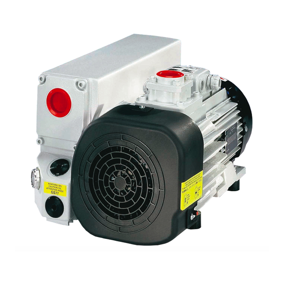
SOGEVAC
SV40 B / SV65 B / SV100 B /
SV120 B ATEX Cat 2
Single-stage, oil sealed rotary vane pump.
Operating Instructions 130001815_002_C0
II (i) 2G b IIB+H2 T3 / (o) 2G IIC T4 (10°C <Ta< 40°C) X
Part Numbers
960305A22
960405A22
960505A22
and their variants.
130001815_002_C0
SV 40 B – 65 B – 100 B – 120 B ATEX Cat 2
11/2016
1 / 74
Advertisement
Table of Contents

Related Manuals for LEYBOLD SOGEVAC SV120 B ATEX Cat 2


Summary of Contents for LEYBOLD SOGEVAC SV120 B ATEX Cat 2
- Page 1 ® SOGEVAC SV40 B / SV65 B / SV100 B / SV120 B ATEX Cat 2 Single-stage, oil sealed rotary vane pump. Operating Instructions 130001815_002_C0 II (i) 2G b IIB+H2 T3 / (o) 2G IIC T4 (10°C <Ta< 40°C) X Part Numbers 960305A22 960405A22...
-
Page 2: Table Of Contents
Shutdown ....................40 Ultimate pump pressure ................40 Maintenance ..................... 41 Safety Information ..................41 Maintenance Intervals ................. 42 Service at Leybold facilities ................. 43 Maintenance Work ..................44 Trouble shooting ....................52 Spare parts ....................... 54 130001815_002_C0 SV 40 B – 65 B – 100 B – 120 B ATEX Cat 2... -
Page 3: Important Safety Information
Note provided within these Operating Instructions. ® The Leybold SOGEVAC SV40 B – SV65 B – SV 100 B – SV120 B ATEX Cat 2 have been designed for safe and efficient operation when used properly and in accordance with these Operating Instructions. It is the responsibility of the user to carefully read and strictly observe all safety precautions described in ®... - Page 4 Liquid and solid particles or dust must not enter into the pump. Install the adequate filters, separators and/or condensers. In case of doubt consult Leybold. The intake line of the pump must never be connected to a device with over atmospheric pressure.
-
Page 5: Description
Description Description ® SOGEVAC pumps are designed for pumping of inert gases in the range of rough vacuum, between atmospheric pressure and end pressure of the pump. When removing condensable vapours, a gas ballast valve must be installed. Principle of operation ®... - Page 6 Description Unintentional venting of the vacuum chamber as well as oil suck back when Warning shutting down the pump are prevented by the integrated anti suck back valve. This valve is not a safety device and its correct operation & tightness can only be assured if the valve plate &...
- Page 7 Description www.europa.eu.int/comm/employment_social/health_safety/publicat/com_199 9_92_ce_en.pdf www.europa.eu.int/comm/employment_social/health_safety/publicat/com_199 9_92_ce_de.pdf www.europa.eu.int/comm/employment_social/health_safety/publicat/com_199 9_92_ce_fr.pdf Ignition temperatures of gases / vapours that may be present: The pump is only suitable for use in situations in which potentially explosive gas or vapour atmospheres have an ignition temperature greater than 200°C. Ignition temperatures of gases and vapours can be obtained from the MSDS (Material Safety Data Sheet).
- Page 8 NOTE: Higher maximum surface temperatures will occur if the pump is filled and used with oils other than Leybold type LVO 210. This is caused by the poorer lubricating and cooling characteristics of other oils in particular PFPE oils.
- Page 9 CLC/TR 50404:2003 Electrostatics - Code of practice for the avoidance of hazards due to static electricity.) NOTE: Only original Leybold replacement exhaust gas filter cartridges and gas inlet filter cartridges should be used as these have a special construction to ensure earthing.
-
Page 10: Technical Characteristics Sv40 B
Description Technical characteristics SV40 B SV40 B 50 Hz 60 Hz Nominal speed m3. h Pumping speed m3. h 38.5 ≤ 0. 5 ≤ 0. 5 Ultimate partial pressure mbar without gas ballast Ultimate total pressure with mbar d 1.5 d 1.5 standard gas ballast Ambient temperature... -
Page 11: Technical Characteristics Sv65 B
Description Technical characteristics SV65 B SV65 B 50 Hz 60 Hz Nominal speed m3. h Pumping speed m3. h ≤ 0. 5 ≤ 0. 5 Ultimate partial pressure mbar without gas ballast Ultimate total pressure with mbar d 1.5 d 1.5 standard gas ballast Ambient temperature 10 …... -
Page 12: Technical Characteristics Sv100 B
Description Technical characteristics SV100 B SV100 B 50 Hz 60 Hz Nominal speed m3. h 97.5 Pumping speed m3. h 87.5 ≤ 0. 5 ≤ 0. 5 Ultimate partial pressure mbar without gas ballast Ultimate total pressure with mbar d 1.5 d 1.5 standard gas ballast Ambient temperature... -
Page 13: Technical Characteristics Sv120 B
Description Technical characteristics SV120 B SV120 B 50 Hz 60 Hz Nominal speed m3. h Pumping speed m3. h ≤ 0. 5 ≤ 0. 5 Ultimate partial pressure mbar without gas ballast Ultimate total pressure with mbar d 1.5 d 1.5 standard gas ballast Ambient temperature 10 …... - Page 14 Description Dimensional drawing SV40 B Fig 1.1 130001815_002_C0 SV 40 B – 65 B – 100 B – 120 B ATEX Cat 2 11/2016 14 / 74...
- Page 15 Description Dimensional drawing SV65 B Fig 1.2 130001815_002_C0 SV 40 B – 65 B – 100 B – 120 B ATEX Cat 2 11/2016 15 / 74...
- Page 16 Description Dimensional drawing SV100 B & SV120 B Fig 1.3 130001815_002_C0 SV 40 B – 65 B – 100 B – 120 B ATEX Cat 2 11/2016 16 / 74...
- Page 17 Description Pumping speed curves 50 Hz SV40 B & SV65 B SV100 B 130001815_002_C0 SV 40 B – 65 B – 100 B – 120 B ATEX Cat 2 11/2016 17 / 74...
- Page 18 Description Pumping speed curves 50 Hz SV120 B 130001815_002_C0 SV 40 B – 65 B – 100 B – 120 B ATEX Cat 2 11/2016 18 / 74...
- Page 19 Description Pumping speed curves 60 Hz SV40 B & SV65 B SV100 B 130001815_002_C0 SV 40 B – 65 B – 100 B – 120 B ATEX Cat 2 11/2016 19 / 74...
- Page 20 Description Pumping speed curves 60 Hz SV120 B 130001815_002_C0 SV 40 B – 65 B – 100 B – 120 B ATEX Cat 2 11/2016 20 / 74...
-
Page 21: Ordering Information
Description Ordering Information Size Part-Nr. Inside Outside Inside Outside ATEX Marking temp. temp. gas group class class group SV40 B 960305A22 IIB & H2 II (i) 2G b IIB+H2 T3 / (o) 2G IIC T4 (10°C <Ta< 40°C) X SV65 B 960405A22 IIB &... - Page 22 Description T3 & T4 Temperature Class: Classification of equipment into classes depending on their maximum surface temperature according to the following table: Temperature class Maximum surface temperature (°C) Gases and vapours used with these pumps should have an ignition temperature greater than 200°C.
- Page 23 Description Connections Pump SV40 B - SV65 B - SV100 B – SV120 B Intake connection G1 1/4’’ Exhaust connection G1 1/4’’ Rubber feet M8 female thread for SV40 B & SV65 B connection M10 female thread for SV100 B & SV120 B Gas ballast Air taken in coupling housing or DN 16 ISO-KF for inert gas connection.
-
Page 24: Connection Fittings Pump Intake
Description Connection fittings pump intake Item Description Part-Nr. Union coupling + seal 711 18 023 Nipple 711 18 033 Elbow 90° 711 18 213 Dust filter with polyester 9714 57 120 cartridge SV40 B & SV65 B Replacement polyester 9714 57 180 cartridge SV40 B &... -
Page 25: Accessories & Roots Combinations For Sv100 B & 120 B
9714 57 180 9714 57 180 9714 57 190 9714 57 190 Only original Leybold parts are to be used in the pumps. A non respect of this Warning will entail a loss of the pump’s ATEX certification. 130001815_002_C0 SV 40 B – 65 B – 100 B – 120 B ATEX Cat 2... -
Page 26: Lubricants
The Leybold LVO 210 oil is an ester oil particularly suited for the SV40 B – 65 Warning B - 100 B & 120 B ATEX pumps. Only original Leybold LVO 210 oil is to be used in the pumps. A non respect of this will entail a loss of the pump’s ATEX certification. -
Page 27: Transport And Storing
We recommend that you contact the service from Leybold. 130001815_002_C0 SV 40 B – 65 B – 100 B – 120 B ATEX Cat 2... -
Page 28: Installation
Installation Installation It is essential to observe the following instructions step by step to ensure safe Warning start-up. Start-up may only be conducted by trained ATEX specialists. Before installing the pump you must reliably disconnect it from the electrical power supply and prevent the pump form running up inadvertently. Observe all safety regulations. - Page 29 Exhaust pipe material must be resistant to pumped gases. Warning Any pump or accessory modification and the use of non Leybold approved pump condition sensors are prohibited without our written consent. Otherwise, the CE Declaration & ATEX certification become void.
-
Page 30: Electrical Connections
Installation Electrical connections Ensure that incoming power to the pump is off before wiring the motor or Warning altering the wiring. The specific wiring and instructions for installation in potentially explosive atmospheres given in the manual for the electric motor must be followed. - Page 31 Installation Motor protection device (on given variants only) To protect the motor windings against a variety of operational malfunctions, the motor is fitted with protection device, which must be connected. PTC thermistors acc. to IEC 60034-1 and DIN 44081/440823 are temperature dependent, semi-conductor devices embedded in the motor windings.
- Page 32 Pump System Overview (Example) 130001815_002_C0 SV 40 B – 65 B – 100 B – 120 B ATEX Cat 2 11/2016 32 / 74...
- Page 33 Decision Diagram °C 103,9 107,79 111,67 115,54 138,51 142,29 146,07 149,83 153,58 °C 119,4 123 ,24 127,08 130,9 134,71 PT100 resistance table 130001815_002_C0 SV 40 B – 65 B – 100 B – 120 B ATEX Cat 2 11/2016 33 / 74...
- Page 34 Wiring diagram (Example) 130001815_002_C0 SV 40 B – 65 B – 100 B – 120 B ATEX Cat 2 11/2016 34 / 74...
- Page 35 Electrical diagram (Example) 130001815_002_C0 SV 40 B – 65 B – 100 B – 120 B ATEX Cat 2 11/2016 35 / 74...
- Page 36 Electrical diagram (Example) 130001815_002_C0 SV 40 B – 65 B – 100 B – 120 B ATEX Cat 2 11/2016 36 / 74...
-
Page 37: Start-Up
Installation Start-up Control Parameters for the Ignition Prevention System Caution Temperature Oil Casing Oil Level Sensor PT100 Pressure Sensor Sensor Alarm Value 105 °C 500 mbar rel. (140.38 Ohm) (7.2 mA) Pump Stop Value 115 °C 650 mbar rel.* At switching to and Timer (144.16 Ohm) (8.16 mA). -
Page 38: Operation
Operation Operation Operation To avoid overloading the motor, do not start the pump more than six times Warning within one hour. If frequent starts are needed, the pump shall run continuously and be linked to the vacuum vessel by means of a valve. In that case, regulation will be made by the valve and not by start/stop of the pump. - Page 39 Changing the type of GB can change the ATEX temperature class ! Consult us before any GB retrofit is undertaken ! Such a modification must be done by Leybold Service only, and the pump will bear a new P/N.
-
Page 40: Shutdown
Operation Shutdown Under normal circumstances, all that you need do is to switch off the pump. Warning ® The intake port of the SOGEVAC contains an anti-suck back valve, which closes the intake port when the pump is shut down, to avoid the pump oil being sucked back into the vacuum chamber. -
Page 41: Maintenance
Never mount used seals; always mount new seals. Only the use of genuine Leybold parts is allowed ! Any integration of non Leybold parts or non authorized repairs will cancel the pump ATEX certification and will waive all Leybold ATEX responsibilities. -
Page 42: Maintenance Intervals
Maintenance Maintenance Intervals The intervals stated in the maintenance schedule are approximate values for Warning normal pump operation. Unfavourable ambient conditions and/or aggressive media may significantly reduce the maintenance intervals. Maintenance job Frequency Section Checking the oil level Daily. 5.4.A Checking the oil condition Depends of process, at least weekly. -
Page 43: Service At Leybold Facilities
Also incorrect maintenance can cause a pump temperature increase, which can influence the pump ATEX temperature rating ! In connection with this, you may be interested in the Leybold practical seminars, in which maintenance, repair and testing information for the ®... -
Page 44: Maintenance Work
Maintenance Maintenance Work 5.4.A Checking the oil level The pump’s oil level during operation must always be between the middle and top edge of the oil-level glass. When necessary, switch off the pump and add the correct quantity of oil. Overfilling leads to oil losses at high intake pressures High oil consumption often indicates that exhaust filters are clogged (See 5.4.D). - Page 45 Maintenance 5.4.C Oil change Tool required : oil filter key (710 73 532) Warning Always change the oil when the pump is switched off but still at working temperature. If there is a risk of the oil being polymerized by the connected process, change the oil immediately after operation of the pump.
- Page 46 Maintenance 5.4.D Replacing the Exhaust Filters Tools required : - Allen key 6 mm. - Box wrench 10 mm. Warning When the exhaust filter elements are clogged, the over pressure (bypass) valves open and the filters are bypassed. Oil mist at the exhaust, and/or high oil consumption are signs that the exhaust filters are clogged.
- Page 47 Maintenance Observe the safety regulations. Important When disposing of used exhaust filters please observe the relevant environmental regulations! Never mount used seals; always mount new seals. 130001815_002_C0 SV 40 B – 65 B – 100 B – 120 B ATEX Cat 2 11/2016 47 / 74...
- Page 48 Maintenance 5.4.E Checking the float valve Tools required : Allen Key 6 mm If the pressure does not fall below approx. 5 mbar during pump operation, check the tightness of the float valve. Remove the exhaust filter (ExF) with the exhaust flange. Remove the pin (54) and pull the float valve assembly out of the float chamber.
- Page 49 Maintenance Checking the Anti-Suck back Valve Tools required : - Allen key 6 mm - Adjusting ring: 710 72 283 Keep the anti-suck back valve clean to ensure proper operation of the pump. In any application we strongly recommend installing an ATEX polyester dust filter upstream (see Section 1.4).
- Page 50 To be done in case of specific pump servicing. 5.4.I Replacement of electrical motor Please consult Leybold for specific maintenance works to be carried e.g. bearing replacement. The motor can only be exchange with an identical one for the same manufacturer and ATEX marking.
- Page 51 Maintenance 5.4.K Procedure for Checking the Ignition Prevention Warning System A complete functionality test of the ignition prevention system has to be carried before the pump is brought into service and after each maintenance operation at the pump or at least once a year. If necessary the over temperature sensor should be re-calibrated.
-
Page 52: Trouble Shooting
Trouble shooting Trouble shooting 130001815_002_C0 SV 40 B – 65 B – 100 B – 120 B ATEX Cat 2 11/2016 52 / 74... - Page 53 Trouble shooting * Reference section: This column refers to the section in the Operating Instructions that contains the applicable repair information. 130001815_002_C0 SV 40 B – 65 B – 100 B – 120 B ATEX Cat 2 11/2016 53 / 74...
-
Page 54: Spare Parts
Consumables and main spare parts kits for SOGEVAC pumps are usually available on stock at Leybold’s service centres. The list of these parts is given here after and in the spare parts table where the contents of each kits is detailed. - Page 55 Spare parts SV40 B ATEX CAT 2 130001815_002_C0 SV 40 B – 65 B – 100 B – 120 B ATEX Cat 2 11/2016 55 / 74...
- Page 56 Spare parts SV40 B ATEX CAT 2 Item Designation Beschreibung Désignation Part-Nr. Pos. Sach-Nr Référence OIL CASING OELKASTEN CARTER 971464040 GLASS OIL SIGHT GLASS GLASS OELSCHAUGLASS VOYANT D'HUILE 3/4 BSP VERRE 71219480 KIT GENERATOR LEST AIR GENERATOR GASBALLAST KIT GENERATEUR GAS BALLAST KIT 971464030 COUPLING ATEX CAT2 KUPPLUNG ATEX CAT2...
- Page 57 Spare parts SV40 B ATEX CAT 2 MAINTENANCE KIT REFERENCE 971464100 INCLUDES: WARTUNGS KIT SACH-NR. 971464100 ENTHAELT: KIT MAINTENANCE REFERENCE 971464100 COMPREND: Quantity. Designation Beschreibung Désignation Anzahl Quantité Protection cover Schutzdeckel Cape de protection Sticker Aufkleber Etiquette Exhaust flange Auslassdeckel- Joint bride gasket Dichtung...
- Page 58 Spare parts SV40 B ATEX CAT 2 REPAIR KIT REFERENCE 971464110 INCLUDES: REPARATUR KIT SACH-NR. 971464110 ENTHAELT: KIT REPARATION REFERENCE 971464110 COMPREND: Quantity. Designation Beschreibung Désignation Anzahl Quantité Exhaust valve Auslassventil Lame échapp. Valve stop Auslassventil- Contre lame Anschlag Mounting Montageanleitung Notice montage instructions valves...
- Page 59 Spare parts SV65 B ATEX CAT 2 130001815_002_C0 SV 40 B – 65 B – 100 B – 120 B ATEX Cat 2 11/2016 59 / 74...
- Page 60 Spare parts SV65 B ATEX CAT 2 Item Designation Beschreibung Désignation Part-Nr. Pos. Sach-Nr Référence OIL CASING OELKASTEN CARTER 971463910 GLASS OIL SIGHT GLASS GLASS OELSCHAUGLASS VOYANT D'HUILE 3/4 BSP VERRE 71219480 KIT GENERATOR LEST AIR GENERATOR GASBALLAST KIT GENERATEUR GAS BALLAST KIT 971463940 COUPLING ATEX CAT2 KUPPLUNG ATEX CAT2...
- Page 61 Spare parts SV65 B ATEX CAT 2 MAINTENANCE KIT REFERENCE 971463990 INCLUDES: WARTUNGS KIT SACH-NR. 971463990 ENTHAELT: KIT MAINTENANCE REFERENCE 971463990 COMPREND: Quantity. Designation Beschreibung Désignation Anzahl Quantité Protection cover Schutzdeckel Cape de protection Sticker Aufkleber Etiquette Exhaust flange Auslassdeckel- Joint bride gasket Dichtung...
- Page 62 Spare parts SV65 B ATEX CAT 2 REPAIR KIT REFERENCE 971464000 INCLUDES: REPARATUR KIT SACH-NR. 971464000 ENTHAELT: KIT REPARATION REFERENCE 971464000 COMPREND: Quantity. Designation Beschreibung Désignation Anzahl Quantité Exhaust valve Auslassventil Lame échapp. Valve stop Auslassventil- Contre lame Anschlag Mounting Montageanleitung Notice montage instructions valves...
- Page 63 Spare parts SV100 B ATEX CAT 2 130001815_002_C0 SV 40 B – 65 B – 100 B – 120 B ATEX Cat 2 11/2016 63 / 74...
- Page 64 Spare parts SV100 B ATEX CAT 2 Item Designation Beschreibung Désignation Part-Nr. Pos. Sach-Nr Référence OIL CASING OELKASTEN CARTER 971463580 GLASS OIL SIGHT GLASS GLASS OELSCHAUGLASS VOYANT D'HUILE 3/4 BSP VERRE 71219480 KIT GENERATOR LEST AIR GENERATOR GASBALLAST KIT GENERATEUR GAS BALLAST KIT 971463590 COUPLING ATEX CAT2 KUPPLUNG ATEX CAT2...
- Page 65 Spare parts SV100 B ATEX CAT 2 MAINTENANCE KIT REFERENCE 971463640 INCLUDES: WARTUNGS KIT SACH-NR. 971463640 ENTHAELT: KIT MAINTENANCE REFERENCE 971463640 COMPREND: Quantity. Designation Beschreibung Désignation Anzahl Quantité Protection cover Schutzdeckel Cape de protection Sticker Aufkleber Etiquette Exhaust flange Auslassdeckel- Joint bride gasket Dichtung...
- Page 66 Spare parts SV100 B ATEX CAT 2 REPAIR KIT REFERENCE 971463650 INCLUDES: REPARATUR KIT SACH-NR. 971463650 ENTHAELT: KIT REPARATION REFERENCE 971463650 COMPREND: Quantity. Designation Beschreibung Désignation Anzahl Quantité Exhaust valve Auslassventil Lame échapp. Valve stop Auslassventil- Contre lame Anschlag Mounting Montageanleitung Notice montage instructions valves...
- Page 67 Spare parts SV120 B ATEX CAT 2 130001815_002_C0 SV 40 B – 65 B – 100 B – 120 B ATEX Cat 2 11/2016 67 / 74...
- Page 68 Spare parts SV120 B ATEX CAT 2 Item Designation Beschreibung Désignation Part-Nr. Pos. Sach-Nr Référence OIL CASING OELKASTEN CARTER 971463580 GLASS OIL SIGHT GLASS GLASS OELSCHAUGLASS VOYANT D'HUILE 3/4 BSP VERRE 71219480 GENERATOR KIT w BIG GENERATOR KIT m. GROSSEM KIT GENERATEUR avec GROS LA EK971455591 GASBALLAST...
- Page 69 Spare parts SV120 B ATEX CAT 2 MAINTENANCE KIT REFERENCE 971463640 INCLUDES: WARTUNGS KIT SACH-NR. 971463640 ENTHAELT: KIT MAINTENANCE REFERENCE 971463640 COMPREND: Quantity. Designation Beschreibung Désignation Anzahl Quantité Protection cover Schutzdeckel Cape de protection Sticker Aufkleber Etiquette Exhaust flange Auslassdeckel- Joint bride gasket Dichtung...
- Page 70 Spare parts SV120 B ATEX CAT 2 REPAIR KIT REFERENCE EK9714636REP INCLUDES: REPARATUR KIT SACH-NR. EK9714636REP ENTHAELT: KIT REPARATION REFERENCE EK9714636REP COMPREND: Quantity. Designation Beschreibung Désignation Anzahl Quantité Exhaust valve Auslassventil Lame échapp. Valve stop Auslassventil- Contre lame Anschlag Mounting Montageanleitung Notice montage instructions valves...
- Page 71 EU Declaration 130001815_002_C0 SV 40 B – 65 B – 100 B – 120 B ATEX Cat 2 11/2016 71 / 74...
- Page 72 Declaration of Contamination 130001815_002_C0 SV 40 B – 65 B – 100 B – 120 B ATEX Cat 2 11/2016 72 / 74...
- Page 73 Notes Notes 130001815_002_C0 SV 40 B – 65 B – 100 B – 120 B ATEX Cat 2 11/2016 73 / 74...
- Page 74 130001815_002_C0 SV 40 B – 65 B – 100 B – 120 B ATEX Cat 2 11/2016 74 / 74...
Need help?
Do you have a question about the SOGEVAC SV120 B ATEX Cat 2 and is the answer not in the manual?
Questions and answers