
Related Manuals for Accu-Scope 3025-LCD


Summary of Contents for Accu-Scope 3025-LCD
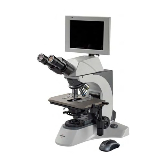
- Page 1 MANUAL 3025-LCD MICROSCOPE SYSTEM 73 Mall Drive, Commack, NY 11725 • 631-864-1000 (P) • 631-543-8900 (F) www.accu-scope.com • info@accu-scope.com...
-
Page 2: Table Of Contents
Table of Contents Ⅰ. Introduction ..................3 1.1 About LCD Digital Microscope .................... 3 1.2 Features ..........................3 1.3 System Specification ......................4 1.4 Camera Specification ......................5 1.5 Microscope Specification ..................... 6 Ⅱ. Structure and Installation ..............7 2.1 Structure ..........................7 2.2 Working location ........................ - Page 3 (4) The PC begins to receive images ................38 4.3.2 Wired Network ......................40 (1) Link the LCD microscope to the LAN ................. 40 (2) Link the PC to the LAN ....................41 (3) The LCD microscope begin to send images ............. 42 (4) The PC begin to receive images ................
-
Page 4: Ⅰ. Introduction
Ⅰ. Introduction 1.1 About LCD Digital Microscope New generation of the microscopes! This LCD digital microscope is a brand new system that has an embedded system. With a 8.4” LCD screen, user-friendly interface, powerful processing function (real-time preview, dynamic calibrating and measuring), multiple peripheral interfaces, and comfortable design;... -
Page 5: System Specification
1.3 System Specification ARM926EJ embedded system CPU 16KB I-Cache, 16KB D-Cache Support full-duplex video with resolution up to VGA(640x480), and frame rate 30fps Image zooming, picture in picture, image post processing. Real time operating system WINCE5.0, supported by MMU ... -
Page 6: Camera Specification
Measurement function Image measurement: Calibration and real-time dynamic image measurement, After calibration, can using physical length unit to measure dynamic images, such as micron, millimeter, inch; Support several basic measurement tools, as cross ruler, rectangle ruler and so on; ... -
Page 7: Microscope Specification
Can rotate at maximum 30°elevation angle and Observation LCD Screen 180°pivoting Accessories Data Wire, Touching Pen, Mouse, Power Adaptor 1.5 Microscope Specification ● Viewing Head Compensation Free binocular head, 30° inclined, Interpupillary 48-75mm ● Wide Field Eyepiece WF 10×/18 Eyepiece ○... -
Page 8: Ⅱ. Structure And Installation
Ⅱ. Structure and Installation 2.1 Structure Structure is as the views below: Capture button Power Switch SD Card interface Audio output Microphone USB Port, can link with USB disk, keyboard, mouse and so on Mini USB Port Capture button Power Switch Reset the system Handwriting Pen Position for... -
Page 9: Working Location
WI-FI Indicator Light Microphone Power Indicator Light 8.4” TFT LCD Screen 2.2 Working Location Choose a working location without direct light, place the equipment far away from window and without facing window, since the direct light will affect the image contrast and observation. Working conditions of digital microscope: 1)Environment temperature: 0℃-40℃, max relative humidity: 85%. -
Page 10: (B) Open The Soft Keyboard
design, especially designed for including or embedding in mobile and other space-constrained devices. Actually, it is an electronic device operation system, and "CE" is reported to have originally stood for "Consumer Electronics." Standard communications support is also built into Windows CE, enabling access to the Internet to send and receive e-mail or browse the World Wide Web. -
Page 11: (C) The Mouse Right Click Function
Click “Hide Input Panel” (c) The mouse right click function If you use the mouse, you can use the right key of the mouse for the right click for more than 2 seconds function. But if you use the handwriting pen, click for the system to respond as a right click. -
Page 12: The Software - Nms
3.2 The software - NMS (a) Main function NMS is a software especially designed for Windows CE system. This special software makes it very easy to capture, record, calibrate and measure digital images. The main function is as follows: 1) Real time preview images 2) Adjust the color 3) Capture images 4) Record videos... -
Page 13: (C) Image Effect Adjust
2. Double click the icon on the desktop. The main interface displays as shown below: The software is divided into 4 parts: a) Video Preview: display real-time dynamic image, resolution 640x480, b) Tools: Located on the right of the main window, there are various tools, buttons and icons. - Page 14 Press the Auto WB button, the system will do auto white balance. Press again to manual white balance. Attention: If you Auto White Balance set it to auto white balance, you can not adjust the R G B values. Press the Auto Exp button, the system will do auto exposure. Press again to manual Exposure.
- Page 15 Examples: Vertical Flip: Original Image After click the Flip button Horizontal Flip: Original Image After click the Mirror button Vertical and Horizontal Flip: Original Image After click both the Flip and mirror button...
-
Page 16: (D) Buttons Function
Color parameters: Use the slider to adjust the gain of the camera. It works only at manual white balance station. Use the slider to adjust the Green gain of the camera. It works only at manual white balance station. Use the slider to adjust the Blue gain of the camera. - Page 17 Click “Record” to capture an active video (click again to stop recording). In the mean time, the status bar displays “Recording” and the button changes to “Stop”, Click stop to stop recording. And the status bar will display the captured videos name and &...
- Page 18 4. Set the IP address of the target PC. And send 1. Set the Capture the images to the PC Parameter receiving end. See Part IV Network Operation. 2. The image 5. Reset the camera store folder when the camera works wrong.
-
Page 19: (E) Dimension Calibration And Dynamic Measurement
The captured videos are stored in the „video‟ folder in the SD Card. Set the IP address of the target PC and send the image data to it. See Part IV Network Operation. If the camera doesn‟t work, click the „Reset‟ button to reset the camera. - Page 20 Click “Image Click “Measure” Effect Adjust” Click “Measure”, the system will switch from the “Image Effect Adjust” to the “Measure”. Click “Image Effect Adjust”, the system will switch from the “Measure” to the “Image Effect Adjust”.
-
Page 21: ① Dimension Calibration
Calibration. Reticle ruler. Line measurement Rectangle measurement. Recovery to the default setting. Set the color of the measure tools. Dimension Calibration ① Here the objective is 10X and the micrometer is 0.1mm. 1. Put a micrometer on the stage; select the objective (example here is 10X), focus the microscope to make the micrometer display clearly on the LCD screen. - Page 22 Click this button 3. Click the icon on the command bar, there will come out an adjustable calibrating line. 4. Move the line and set the begin point.
- Page 23 5. Set the end point. 6. Set the objective magnification, length unit and input the actual length (with the keyboard or the soft keyboard).
- Page 24 7. Click “OK”, the system will calculate the dimension data that just has calibrated (the actual length of each pixel) by itself and displays in the control panel, as follows: The dimension calibration of 10X objective has been finished. Repeat the above steps to calibrate 4X, 40X and 100 X.
-
Page 25: ② Length Measurement
Length Measurement ② 1. Click the icon on the command bar. 2. Move the line to the place you want to measure. Set the begin point and the end point of the line, the system will then calculate the length itself according to the dimension you have just calibrated. -
Page 26: ③ Rectangle Measurement
Rectangle Measurement ③ 1. Click the rectangle button, a rectangle tool appears; click the center or the four corners of the rectangle with the mouse or writing pen; you can drag the seletction to magnify or reduce the rectangle. Color Selecting ④... -
Page 27: ⑤ Reticle Ruler
2. All the tools color has been changed into mauve. Reticle Ruler ⑤ 1. Click the reticle button. There will be a reticle tool on the image, click the center of the reticle with the mouse or writing pen, a red square in the center of the reticle will appear;... - Page 28 following the square. At the same time, the control panel will display the minimum scale value of the current reticle after dimension calibrating. 2. Click the center of the reticle and a square appears; you can move the square to any place you want.
-
Page 29: ⑥ Store The Measurement Result
⑥ Store the measurement result In order to store the measurement result, you should set the resolution to 640x480(Reserve ruler) first, as the picture below. - Page 30 Capture an image with the measurement result. Preview the captured image ‘photo27.bmp’.
-
Page 31: (F) Image Preview
(f) Image Preview Window Enlarge preview the partial of image in the red rectangle. Last Page Next Page Panoramic image, move the red rectangle to adjust the partial of image to enlarge preview. Switching Delete the select image. video preview Image Index Bar: Displays the captured images Double click the select image to preview. -
Page 32: (G) Attention: If The System Halted
mouse or click the select image directly on the touch screen by the handwriting pen for more than 2 seconds, the system will respond as a right click, and a right key menu appears; select “Delete”. (3) Switch back to video preview window: Click the video icon to return to video preview window. -
Page 33: Communication Model
What is WIFI? "WIFI" means "wireless fidelity". The term "WIFI" refers to certain kinds of wireless local area networks, or WLAN (as opposed to LAN, or computers that are networked together with wires). 4.2 Communication Model (a) Network Communication (With the LAN) 1. -
Page 34: (B) Point To Point Model (Without The Lan)
(b) Point to Point Model (Without the LAN) There are two ways to communicate with the PC without the LAN: One is by WIFI function (wireless), and the other is by network cable (here is crossover cable). We call both of them point-to-point communication. -
Page 35: (D) Visit The Internet
(d) Visit the Internet Attention: We can use the LCD microscope to visit a website, but we can not receive the microscope images though the internet, just browse the web pages. 4.3 Network Communication 1. WIFI function 1. WIFI function 2. -
Page 36: Link The Lcd Microscope To The Lan
The LCD Digital Microscope communicates with the PC by a router (LAN). (1) Link the LCD microscope to the LAN (1) Start your system Window CE. (2) A dialog appears listing all the networks the system has searched. You can also get this dialog box by double clicking the icon on the task bar. - Page 37 If you use the wireless network, please make sure your PC has a wireless network card and supports wireless function. (1) Double click the icon on the task bar Click „Connect‟ button (2) Click the „Connect‟ button. The PC will connect the router and get the IP address by itself.
-
Page 38: The Lcd Microscope Begins To Send Images
(3) Now the wireless icon on the task bar displays as , double click it. Click “Support” (4) Check the IP address, and record it. (3) The LCD microscope begins to send images (1) Start your software “NMS”... -
Page 39: The Pc Begins To Receive Images
, a “Configure” dialog box appears. Set the IP Address (2) Click the button (The IP Address of the PC), port number (rang from 2000 to 5000), and click “Start” button, the system begins to send the data via WIFI wireless net. The button now changes from Start to Stop;... - Page 40 The port number should the same as the NMSClient. Click „Receive‟ to begin Attention: The port number of video sender and the NMSClient should be the same. And make sure your microscope video sender has been started. (4) The NMSClient begins to receive video, and displays the real time video. You can capture images or record videos.
-
Page 41: Wired Network
Set the video saving path Set the image saving path Capture a frame Click this button to capture the video, click again to stop capturing. 4.3.2 Wired Network (1) Link the LCD microscope to the LAN (1) Link the LCD digital microscope to the router with network cable (straight cable) (2) Set the IP address of the LCD digital microscope, and the operation is the same... -
Page 42: Link The Pc To The Lan
Set the IP address, for example Click OK. (2) Link the PC to the LAN (1) Link the PC to the router with network cable (straight cable) (2) Set the IP address of the PC. Note: The PC‟s IP address should in the same LAN as the router. Double click the icon on the task bar Click... -
Page 43: The Lcd Microscope Begin To Send Images
Click “Internet Protocol(TCP/IP) Now we have set the IP address of the PC, if the PC begins to receive, you will find the local area connection status displays as follows: Connected Begin to receive data. (3) The LCD microscope begins to send images... -
Page 44: The Pc Begin To Receive Images
(1) Launch your software “NMS” on the desktop. , a “Configure” dialog box appears. Set the IP Address (2) Click the button as the PC‟s IP address, port number (range from 2000 to 5000), and click “Start” button, the system begins to send the datas. The button now changes from Start to Stop;... - Page 45 The port number should the same as the NMSClient. Click „Receive‟ to begin (4) Wait a minute, the NMSClient begins to receive video, and displays the real time video. You can capture images or record videos. Set the video saving path Set the image saving path Capture a frame...
-
Page 46: Point-To-Point Model
4.4 Point-to-point Model 1. WIFI function 2. Network cable (crossover cable) Attention: 1. Use the WIFI function, the PC receiver must support wireless function, please check whether your network card support wireless function. 2. Use network cable to link the LCD Microscope and PC, the network cable must be a crossover cable. See the part V to know what are straight and crossover cable. - Page 47 Double click “Add New…” Step1. Input a network name. Step3. Set to “Disabled” Step2. Select this box Step4. Click “OK” (5) After setting, there‟s a new point-to-point (computer-to-computer) network has been setup. 1. Select the net you have just set. connection is the one that has a blue circle on the icon,...
-
Page 48: Link The Pc To The New Network
(4) Set the IP address of the LCD digital microscope, the same operation as the Windows XP system. Click “Start-> Settings->Network and Dial-up Connections“; Double click the wireless icon Set the IP address, for example Click OK. (2) Link the PC to the new network Make sure your PC has a wireless network card and the card has the installed driver. - Page 49 on the desktop, click „Properties‟. 1. Right click the My Network Places icon 2. Double click the “Wireless Network Connection”. There will come out a „Wireless Network Connection Status‟ dialog. Or you can also get this dialog by double clicking the icon on the task bar.
- Page 50 3. The system will search the wireless network by itself, please select the Point-to-Point network you have just created. If not, please click the “Refresh network list” on the left control bar. Then click the button “Connect”.
- Page 51 4. Click Properties Click “Properties”...
-
Page 52: The Lcd Microscope Begins To Send Images
Click “Internet Protocol (TCP/IP) Properties” Attention: The IP address should be set to in the same LAN as the LCD digital microscope. (3) The LCD microscope begin to send images (5) Start your measuring software “NMS” , a “Configure” dialog box appears. Set the IP Address (6) Click the button (reference the router), port number (rang from 2000 to 5000), and click the “Start”... -
Page 53: The Pc Begin To Receive Images
(4) The PC begin to receive images (1) Make sure the software NMSClient has been installed in the PC. (2) Launch the “NMSClient” software. (3) Click the Receive button. Attention: The port number of video sender and the NMSClient should be the same. Make sure your microscope video sender has been started. - Page 54 Click “Start” Attention: Sometimes a „windows security Alert‟ dialog box appears -- just click the „Unblock‟ button. (4) The NMSClient begins to receive video, and displays the real time video. You can capture images or record videos. Set the video saving path Set the image saving path...
-
Page 55: By Network Cable (Crossover Cable)
4.4.2 By Network Cable (crossover cable) (1) Set the LCD microscope (1) Link the LCD digital microscope to the PC with network cable (crossover cable) (2) Set the IP address of the LCD digital microscope Click “Start-> Settings->Network and Dial-up Connections“; Double click the wired network icon Set the IP address, for example Click OK. - Page 56 Click “Properties” Click “Internet Protocol(TCP/IP) Now we have set the IP address of the PC, if the PC begins to receive, you will find the local area connection status display as follows:...
-
Page 57: The Lcd Microscope Begin To Send Images
Connected The packets number will be changed if it begins to receive data. (3) The LCD microscope begin to send images (1) Start your software “NMS” , there will come out an “Configure” dialog, set the IP (2) Click the button Address (The IP Address of the PC), port number (range from 2000 to 5000), and click the “Start”... -
Page 58: The Pc Begins To Receive Images
Input the PC‟s IP address. Then click „Start‟ Click “Start” Now we have finished the setting of the LCD digital, and it is sending video, you can click “Stop” to stop sending video. (4) The PC begin to receive images (1) Make sure the software NMSClient has been installed in the PC. - Page 59 The port number should the same as the NMSClient. Click „Receive‟ to begin Attention: The port number of video sender and the NMSClient should be the same. Make sure your microscope video sender has been started. Click “Start”...
-
Page 60: Common Failure And Solution
Attention: Sometimes a „windows security Alert‟ dialog box appears -- just click the „Unblock‟ button. (4) The NMSClient begins to receive video, and displays the real time video. You can capture images or record videos. Set the video saving path Set the image saving path Click this button to... -
Page 61: Electric Section
Common Failure and Solution Codes The failure and solution contains 3 sections: Optical section, mechanical section and electronic section. Here we just give the electronic section 5.1 Electric section (a) Error messages Code5: Indication: Can't save image, please check SD card. Code:5. Solution: The SD card is not in the position, check and put it in the position. -
Page 62: (B) Cannot Switch On The System
Code9: Indication: Capture failed, Code: 9, please reboot device to solve this issue. Solution: Reboot the system to solve the problem. (b) Can not switch on the system Problem: Can not switch on the system or the system can not work. Causes: Power isn‟t connected properly. -
Page 63: (F) No Response On The Touch Screen
Manufacturer Operation hole! Please don‟t use! Data transfer interface; Make sure the line connect tightly with the interface, otherwise it may cause the blur image or unstable system. (f) No respond of the touch screen. Problem: The touch screen isn‟t responding properly to your taps. Causes: The screen stylus is not in the right place. - Page 64 3) There will be a crosshair in the center of the screen. Carefully press and briefly hold stylus on the center of the target. Press the Esc key to cancel. As follows: 4) Repeat as the target moves around the screen. Press the Esc key to cancel. As follows:...
- Page 65 5) New calibration settings have been measured. Press the Enter key to accept the new settings. Press the Esc key to keep the old settings. 6) Now the screen recalibration has been finished, you can use the touch screen again.
-
Page 66: (G) What Are Straight And Crossover Cable
(g) What are Straight and Crossover cable Common Ethernet network cables are straight and crossover cable. This Ethernet network cable is made of 4 pair high performance cable that consists of twisted pair conductors that are used for data transmission. Both ends of the cable are called RJ45 connectors. - Page 67 Crossover Cable Sometimes you will use crossover cable, it's usually used to connect same type of devices. A crossover cable can be used to: 1) Connect 2 computers directly. 2) Connect a router's LAN port to a switch/hub's normal port. (normally used for expanding network) 3) Connect 2 switches/hubs by using normal port in both switches/hubs.
- Page 68 Lastly, if you still not sure which type of cable to be used sometimes, try both cables and see which works. Note: If there is auto MDI/MDI-X feature support on the switch, hub, network card or other network devices, you don't have to use crossover cable in the situation which I mentioned above.
-
Page 69: Maintenance
ACCU-SCOPE INC. This warranty expressly excludes any liability by ACCU-SCOPE INC. for consequential loss or damage on any grounds, such as (but not limited to) the non-availability to the End User of the product(s) under warranty or the need to repair work processes.
Need help?
Do you have a question about the 3025-LCD and is the answer not in the manual?
Questions and answers