
Related Manuals for Accu-Scope 3002


Summary of Contents for Accu-Scope 3002
-
Page 2: Table Of Contents
Table of Contents Safety Notes………………………………………………….…. i Care and Maintenance………………………………………... ii 1. Component Illustration ……………………………………… 1 2. Installation of Components ………………………………….. 2 3. Adjusting Components……………………………………….. 7 4. Operation……………………………………………………… 9 5. Technical Specifications …………………………………….. 12 6. Component List ………………………………………………13 7. Trouble Shooting Guide …………………………………….. 14... -
Page 3: Safety Notes
SAFETY NOTES 1. Open the shipping carton carefully to prevent any accessory, i.e. objectives or eyepieces, from dropping and being damaged. 2. Do not discard the molded Styrofoam container; the container should be retained should the microscope ever requires reshipment. 3. -
Page 4: Care And Maintenance
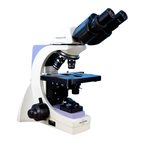
Store the instrument in a cool, dry environment. Cover the microscope with the dust cover when not in use. ACCU-SCOPE microscopes are precision instruments which require periodic servicing to maintain proper performance and to compensate for normal wear. A regular schedule of preventative maintenance by qualified personnel is highly recommended. - Page 5 Binocular Viewing Head bino Eyepiece Nosepiece Objective Body 3002 BINOCULAR MICROSCOPE SERIES...
-
Page 6: Installation Of Components
Installation of Components The diagram shows the numerical order to assemble the microscope. Inspect all optical surfaces for dust and debris; clean if necessary. Do not use force to install any component; all components should be installed without strain. Eyepieces ②... - Page 7 2. Installation Procedure Installation of the Binocular Viewing Head (Figures 1 & 2) Insert the binocular viewing head into the head of the body; ensure that the dovetail is completely seated into the Figure 1 body; tighten the thumb screw. Do not release the head from your hand grip until you are sure the head is installed securely.
- Page 8 Installing the Objectives (Figures 5 &6) 1: Adjust the coarse focus knob until the mechanical stage is at its lowest position. 2. Install the 4x objective into the nosepiece. Then in a clock-wise direction, rotate the nosepiece and install each succeeding higher magnification objective. Inspect the objectives frequently for dirt or oil;...
- Page 9 Installing the Power Cord (Figures 8-9-10) ★ Do not bend or crush the power cord. This could cause the cord to become unusable or dangerous. 1. Before connecting the power cord, make sure the switch ① is in the “off” (O) Figure 8 position.
- Page 10 Installing & Changing the Halogen Bulb(Figures 11, 12 & 13) NOTE: Use only 6volt 20watt halogen lamp. 1: Pull out & remove the condenser set ①. Figure 11 1. Insert halogen lamp ① into the lamp socket. NOTE: Do not touch the glass on the bulb with your bare fingers.
- Page 11 Adjustable Components (Figures 14 & 15) Interpupillary Distance Adjustment Condenser Adjustment Knob Diopter Adjustment Upper Limit Stage Locking Lever Left Fine Focus Knob Variable Intensity Light Switch Left Coarse Focus Knob Figure 14...
- Page 12 Iris Diaphragm Adjustment Lever Right Fine Focus Knob Y Stage Movement Adjustment Knob Right Coarse Focus Knob On/Off Switch X Stage Movement Adjustment Knob Tension Adjustment Collar Figure 15...
-
Page 13: Operation
Operation Adjusting the Illumination (Figures 20 & 21) Connect the power cord; turn on the main switch (Figure 15) to “-” (on). Increase the brightness by rotating the variable intensity knob counterclockwise; turning it clockwise reduces the brightness . Using the lamp in a low intensity will prolong the bulb life. Figure 20 Placement of Slide Specimen (Figure 22) Place the slide on the mechanical stage. - Page 14 Adjusting the Condenser (Figure 24) Turn the condenser focus knob to raise or lower the condenser. The condenser is raised when using high magnification objectives and lowered when using the low magnification objectives. The centering of the condenser and the light axes of the objective factory adjusted.
- Page 15 Adjusting the Eyepiece Diopter (Figure 27) Using the 10x objective and your right eye only, observe your specimen through the right eyepiece and bring it into focus, Then observe the specimen with your left eye only through the left eyepiece. If the specimen is not in focus, rotate the diopter ring①...
- Page 16 SPECIFICATIONS Objective Tube 160mm Length Monocular, Binocular or Trinocular Head, Inclined 30º Viewing Head Interpupillary distance: 55-75mm Eyepiece WF 10x; 18mm field of view Forward Facing Quadruple Nosepiece Nosepiece Objectives Achromatic :4×,10×,SP40×、100×oil Coaxial Coarse and Fine Focusing System, Sensitivity and Graduation of Fine Focus System Focus: 0.002mm.
-
Page 17: Troubleshooting Guide
TROUBLESHOOTING GUIDE If a problem occurs during the course of use, please refer to the tables below before contacting your ACCU-SCOPE distributor. OPTICAL Problem Cause Corrective Measure Revolve the nosepiece to Darkness at the periphery Revolving nosepiece not in click-stop position by... - Page 18 IMAGE PROBLEMS Problem Cause Corrective Measure Image tinged yellow Lamp intensity is too low Adjust the light intensity by rotating the intensity control dial Image is too bright Lamp intensity is too high Adjust the light intensity by rotating the intensity control dial Insufficient brightness Lamp intensity is too low...
- Page 19 United States of America. All items returned for warranty repair must be sent freight prepaid and insured to ACCU-SCOPE INC., 73 Mall Drive, Commack NY 11725 – USA. All warranty repairs will be returned freight prepaid to any destination within the continental United States of America.
Need help?
Do you have a question about the 3002 and is the answer not in the manual?
Questions and answers