
Subscribe to Our Youtube Channel
Related Manuals for Idemia VisionPass


Summary of Contents for Idemia VisionPass
- Page 1 VisionPass Installation guide Copyright 2019 Idemia October 2019 | 2019_2000045728...
- Page 2 Copyright 2019 Idemia October 2019 | 2019_2000045728...
- Page 3 COPYRIGHT © 2020 Idemia. All rights reserved. Reproduction in whole or in part in any form or medium without the express written permission of Idemia is prohibited. The trademarks identified herein are the trademarks of registered trademarks of Idemia, or other third party.
- Page 4 Revision history Version Date Reference Description April 2020 2019_2000045728 Document creation VisionPass - 2019_2000045728...
-
Page 5: Table Of Contents
2.1 > Box opening 2.2 > Components of the initial package 2.3 > Terminal's front view description 2.4 > Terminal's rear view description 2.5 > VisionPass Technical Characteristics 3 / Installation procedure 3.1 > Before proceeding to the installation 3.2 > Installation 3.3 >... - Page 6 9 / Annex 2 : Bibliography 9.1 > How to get the latest versions of documents 9.2 > Documents about the MorphoWave Compact terminal 10 / Annex 3 : Support 10.1 > Troubleshooting 10.2 > Technical Support and Hotline VisionPass - 2019_2000045728...
-
Page 7: Introduction
1 / Introduction VisionPass - 2019_2000045728... -
Page 8: Visionpass Terminal
1.1 > VisionPass terminal To ensure the most effective use of your VisionPass terminal, we recommend that you read this Installation Guide completely. VisionPass - 2019_2000045728... -
Page 9: Scope Of The Document
1.2 > Scope of the document This guide deals with the installation of VisionPass, which is made up of the following list of products: Contactless smartcard reader Regulatory Water VisionPass Marketing Name Biometrics Model Number ® MIFARE Resistant ® ®... -
Page 10: Safety Instructions
In case of building to building connection it is recommended to connect 0V to ground. Ground cable must be connected with the terminal block Power Ground. Note that all connections of the VisionPass terminal described hereafter are of SELV (Safety Electrical Low Voltage) type. -
Page 11: Wiring Recommendations
1.4 > Wiring Recommendations Idemia recommends using a AWG16 gauge and 24V power supply. voltage specified measured product block connector: 12V-24V (-15% / +10%). The voltage drop due to the cable shall be taken into account. The following table shows the maximum... -
Page 12: Regulatory, Safety And Environmental Notices
Compliance with these directives is assessed using applicable European Harmonised Standards. VisionPass terminals are intended to be used for professional application only (buildings, airport...). The full Declaration of Conformity is available on demand to your reseller. Please, provide him the product model name or its Regulatory Model Number (Model on the label). -
Page 13: Usa (Fcc) Regulatory Notices
Changes or modifications not expressly approved by the party responsible for compliance could void the user's authority to operate the equipment. Responsible Party: Idemia Identity & Security FRance 2 place Samuel de Champlain 92400 Courbevoie – France NOTA : This equipment has been tested and found to comply with the limits for a Class B digital device, pursuant to Part 15 of the FCC Rules. -
Page 14: Canada (Ic) Regulatory Notices
20cm with the user, and should not be installed nearby or be used in conjunction with another antenna or transmitter. MPH-AC006B product model incorporates a module that meets Industry Canada's requirement set limits. o IC: JQ6-SE3210 VisionPass - 2019_2000045728... - Page 15 émetteur. Remarque: UL LLC n'a pas vérifié la conformité de ce produit aux normes canadiennes. Le modèle de produit MPH-AC006B comprend un module conforme aux limites établies par Industrie Canada o IC: JQ6-SE3210 VisionPass - 2019_2000045728...
-
Page 16: Others Recommendations
This symbol means do not dispose of your product with your other household waste. Instead, you should protect human health and the environment by handing over your waste equipment to a designated collection point for the recycling of waste electrical and electronic equipment. VisionPass - 2019_2000045728... -
Page 17: Recommendations For Terminal Implementation
Every installation is unique. Sometimes the issues are well defined and can be handled in a standard fashion; sometimes the issues are very specific and may not be immediately recognizable. Idemia recommends following these steps for a successful installation: Plan the installation - Choose the type of hardware required, decide if a network is required, and decide on the location and number of required terminals. - Page 18 To secure properly an access, Idemia recommends installing the VisionPass terminal as a part of the typical Access Control environment described in the figure below. VisionPass Compact Terminal Figure: Implementation Recommendations This environment comprises: The VisionPass terminal itself Its role is to perform one-to-many biometric identification or one-to-one biometric verification, i.e. to identify...
- Page 19 The Controller sends its decision to the VisionPass terminal (which displays access granted or access denied depending on the answer) The VisionPass terminal sends an alarm signal to the Controller as soon as a malicious operation is detected (terminal pulled out from the wall or opened for maintenance operations); refer the paragraph dealing with anti-pulling and anti-tamper switches for more explanations.
-
Page 20: General Description
2 / General description VisionPass - 2019_2000045728... -
Page 21: Box Opening
Extract the wall plate (which is not screwed to the terminal) and keep it separate until the installation of the terminal is completed. The screwing of the product to the wall plate is the last stage of the installation. Figure 1: Box Opening VisionPass - 2019_2000045728... -
Page 22: Components Of The Initial Package
2.2 > Components of the initial package Figure 2: Box Content 1. One (1) Terminal’s body 2. One (1) Wall frame 3. Documentation Package VisionPass - 2019_2000045728... -
Page 23: Terminal's Front View Description
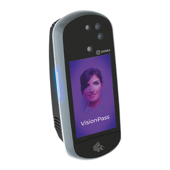
2.3 > Terminal's front view description NIR camera Visible camera IR light 3D cameras LED (power-on) 7’’ WVGA touchscreen LCD speaker microphone contactless area Figure 3: VisionPass terminal front view VisionPass - 2019_2000045728... -
Page 24: Terminal's Rear View Description
2.4 > Terminal's rear view description Power supply Relay Tamper switch RS485 / RS422 GPIO Wiegand RJ45 USB port (for configuration and settings with a USB mass storage key, or installation of a Wi-Fi dongle Figure 4: VisionPass terminal rear view VisionPass - 2019_2000045728... -
Page 25: Visionpass Technical Characteristics
2.5 > VisionPass Technical Characteristics Item Description Access control modes Identification (search for faces in a local database) Authentication with contactless smartcard, with or without face check Multi-factor: identification or authentication Proxy: the access control check is fully driven by a remote system Man Machine Interface 7”... - Page 26 Tamper-pulling detection: one switch closed when product wall mounted, open when pulled out Size and weight W x H x D: 325 mm x 143 mm x 110 mm (12.8” x 5,6” x 4.3”) Weight : 2,1 kg VisionPass - 2019_2000045728...
- Page 27 Storage temperature -25 °C to + 70 °C (-13°F to 158°F) Storage humidity 5% < RH < 95 % The terminal should be installed in controlled lighting conditions Avoid direct exposure to sunlight or to UV lights VisionPass - 2019_2000045728...
-
Page 28: Installation Procedure
3 / Installation procedure VisionPass - 2019_2000045728... -
Page 29: Before Proceeding To The Installation
For an optimal use the terminal must be installed in an area where the lighting conditions are controlled. Avoid direct exposure of the sensor to the sun light and ensure good ambient lighting for face detection if used. VisionPass - 2019_2000045728... -
Page 30: Installation
For UL-294 compliance, an earthed screen in the wire or around all wires to/from product is only required when the wires share space/compartment/tube with high voltage cables. Equipment from the initial package to use One (1) Terminal’s body. One (1) wall plate. VisionPass - 2019_2000045728... -
Page 31: Step By Step Procedure
Avoid direct exposure of the sensor to the sun light. Power supply from electrical source shall be switched off before starting the installation. The strength of the attachment depends on the solidity of the wall on which the terminal is mounted. VisionPass - 2019_2000045728... -
Page 32: Drill The Mounting Holes
Drill in the wall 4 holes with a diameter adapted to screws and fit them with the raw plugs (see Figure 7: Drilling template). Be sure that a sufficient space is reserved in the wall for the passage of cables, in particular for Ethernet. VisionPass - 2019_2000045728... -
Page 33: Make The Connections
3.3.2 > Make the connections Unscrew the connector from the device: Figure 8: Connection - Step 1 VisionPass - 2019_2000045728... - Page 34 Fit the cables through the mounting plate: Figure 9: Connection - Step 2 Then connect the cables: Figure 10: Drilling template and cable connection VisionPass - 2019_2000045728...
- Page 35 Cable for wiring shall be AWG 20 to 24, length shall be adapted to the size of the hole in the wall, to terminal connections, and to the distance between the electric source and the terminal itself. For power supply, IDEMIA recommends using a 24V power supply and AWG16 gauge cable. To ensure water tightness, be sure to bend the cable downward.
-
Page 36: Attach The Base Plate On The Wall
3.3.3 > Attach the base plate on the wall Fix the base plate on the wall with the 4 screws. Figure 12: Base plate fixation on the wall VisionPass - 2019_2000045728... -
Page 37: Attach The Device On The Base Plate
3.3.4 > Attach the device on the base plate VisionPass - 2019_2000045728... -
Page 38: Connect The Connector Assembly On The Device
3.3.5 > Connect the connector assembly on the device Attach the connector assembly on the device with the 4 screws. Don’t forget to screw (x5) Figure 13: Connector assembly on the device VisionPass - 2019_2000045728... -
Page 39: Close The Device On The Base Plate
Detach the device from the plate: first lift the device upwards, then pull it towards you, and hold it. Figure 14: Product closure Do not try to turn the product directly while it is attached on the base plate, as this would definitely damage the plate and the device ! VisionPass - 2019_2000045728... - Page 40 Then rotate the device 90° to align it in the final position in front of the plate. Push the device towards the wall, then downwards until the device is locked on the plate. Figure 15: Product fixation on wall frame VisionPass - 2019_2000045728...
- Page 41 The hardware installation of the product on the wall is complete ! Power can be switched ON just after closing it. If the product has to be stored for a long time (more than 48 hours), don’t forget to restore its configuration before use. VisionPass - 2019_2000045728...
-
Page 42: Electrical Interface
4 / Electrical interface VisionPass - 2019_2000045728... -
Page 43: Wiring Overview
Electrostatic Discharges (ESD). Power supply ground shall not be used for peripheral ground. All other grounds can be used indifferently. Note that all connections of the VisionPass terminal described hereafter are of SELV (Safety Electrical Low Voltage) type. Figure 17: Cabling layout... -
Page 44: Power Supply
If sharing power between devices, each unit must receive 3A (e.g. two units would require a 12VDC, 6A supply). IDEMIA recommends using a 24V power supply and AWG16 gauge cable. The voltage measured on the product block connector of the terminal must be equal to 12V-24V (-15% / +10%). -
Page 45: Output Relay
Resistive load or inductive load; see warning information hereafter for inductive load, The internal relay is designed for at least 100 000 cycles (resistive load). Inductive load management requires a parallel diode for a better contact lifetime. Example of connection for electrical door locks MorphoWave Compact terminal VisionPass - 2019_2000045728... -
Page 46: Tamper Switch
100 mA at 30 VDC max (Resistive load) according to the safety extra low voltage standard. This VisionPass terminal is part of security system; it is customer’s responsibility to connect the tamper switch (contact) to physical access controller, in order to prevent the access to the connector blocks. -
Page 47: Wiegand Wiring
If pull-up’s to 12V have been added on Wiegand IN D0 and Wiegand IN D1 inputs on a previous installation with a MorphoAccess® 500 Series terminal, these resistors must be removed to avoid any damage to the VisionPass terminal. VisionPass - 2019_2000045728... -
Page 48: Wiegand Output
LED1 and the GND wires, and it means “access granted”. The VisionPass terminal uses the timeout of the wait for a low level on the on LED1 wire or LED2 wire as “access denied” answer. - Page 49 (by closing a contact between the LED2 and the GND wires), whatever is the state of the LED1 wire. The VisionPass terminal also considers that the answer of the controller is "access denied" in case of time- out while expecting for a closure between LED1 and GND wires, or between LED2 and GND wires.
-
Page 50: Serial Port Wiring
(Output type required: Open drain or 5V+/-5%) LED IN 2 (option): panel feedback Blue / Red WIEGAND_LEDOUT2 (Output type required: Open drain or 5V+/-5%) Black / Red WIEGAND_GND Ground for Wiegand Figure 25: Serial port wiring – DataClock Output VisionPass - 2019_2000045728... - Page 51 RS422 inverting Receive Green / Black RS422_TX_Y RS422 non inverting Transmit Green / White RS422_TX_Z RS422 inverting Transmit Black / Red RS422_GND Ground Figure 27: Serial port wiring – RS422 RS422 interface is a full duplex communication. VisionPass - 2019_2000045728...
-
Page 52: Gpio Wiring
Single Door Access Control (SDAC) implementation Push button / Motion sensor External Power GPI_0 supply Door GPO_0 strike GPI_1 GPO_1 RELAY_COM RELAY_NO/NC Door contact Figure 29: SDAC wiring If door contact is not used, GPI1 and GPO1 shall be connected together VisionPass - 2019_2000045728... -
Page 53: Ethernet Connection
RJ45 plug pinout is compliant with 10/100 base T, IEEE802.3 Specification. Product is compliant also with MDI or MDI-X. Ethernet cable shall be shielded Default Ethernet configuration By default, VisionPass terminal is configured in STATIC mode with the following configuration: IP Adress : 192.168.1.10; Gateway Adress : 192.168.1.254; Subnet Mask : 255.255.254.0 VisionPass - 2019_2000045728... -
Page 54: Internal Usb Connection
4.10 > Internal USB connection Remove the 4 screws of the cover, as shown on the following drawing. Then remove the cover. Figure 31: Cover removing Then you can see a Mini USB plug. Figure 32: Internal USB connection VisionPass - 2019_2000045728... - Page 55 The internal Mini USB-type B can be used for administration only to connect a mass storage USB key (with a standard Mini USB-type B / USB-type A female OTG adapter). Please refer to VisionPass Administration Guide for more information. USB connection is limited to USB key connection (power consumption shall not exceed...
-
Page 56: Wi-Fi™ Dongle Installation
Product integrating Wi-Fi™ dongle shall not be exposed to temperature exceeding 35°C and shall not be exposed to direct sun. Only Wi-Fi™ USB dongle delivered by Idemia (kit reference 293761928, containing the dongle and the adapter) may be installed with the terminal for WLAN (Wireless Local Area Network) operation. - Page 57 Then plug the Wi-Fi dongle on the provided adapter, connect the adapter on the Mini-USB socket, as described on the following picture: Figure 34: Wi-Fi™ dongle installation Close the product with the cover and tighten the 4 screws. VisionPass - 2019_2000045728...
-
Page 58: User Interface
5 / User interface VisionPass - 2019_2000045728... -
Page 59: Modes For Controlling Access Rights
5.1 > Modes for controlling access rights 5.1.1 > Introduction The VisionPass terminal offers several methods for controlling access rights: it needs to be configured in one of the following four modes: Identification mode, Authentication mode, Multi-factor mode, Proxy mode Refer to VisionPass Administration Guide for more information on Access Control. -
Page 60: Multi-Factor Mode
The VisionPass terminal is driven through an Ethernet (or Wi-Fi™) link using TCP, SSL or TLS protocol. The VisionPass terminal acts as a server: it is either waiting for a command or executing a command. The commands allowed by the VisionPass terminal are described in the VisionPass Host System Interface Specification document. -
Page 61: External Database Mode (Also Called Polling Mode)
5.1.6 > External database mode (also called polling mode) When external database mode is activated, the VisionPass terminal does not verify user template in its local database. This mode is useful when the user templates are stored in external database. -
Page 62: Accessories, Software Licenses And Pc Applications
6 / Accessories, Software Licenses and PC Applications VisionPass - 2019_2000045728... -
Page 63: Compatible Accessories, Licenses And Software
6.1 > Compatible Accessories, Licenses and Software The following items can be ordered directly to Idemia or to an official distributor, so as to enjoy all the features of your VisionPass terminal: Power supply units, Contactless smartcards: MIFARE® 1k, 4k; DESFire® 2k, 4k, 8k, WI-FI PACK: containing a Wi-Fi™... -
Page 64: Compatible Pc Applications
6.2 > Compatible PC applications VisionPass terminals are fully compatible with: MorphoManager (version 14.3 or higher) MorphoBioToolBox (version 4.4.1.0 or higher) VisionPass - 2019_2000045728... -
Page 65: Recommendations
7 / Recommendations VisionPass - 2019_2000045728... - Page 66 The terminal clock has a +/-10 ppm typical time deviation at +25°C (roughly around +/- 6 sec per 48 hours). At lower and higher temperature (but within normal operating temperatures), deviation may be more important (worst case: - 14 seconds per 48 hours). VisionPass - 2019_2000045728...
- Page 67 Use a dry cloth to clean the terminal, especially the front face. It is recommended that the product be cleaned daily to ensure the best performance level over its lifetime. The use of acid liquids, alcohol or abrasive materials is prohibited. Use dry air spray to remove the dust out of the sensor glass. VisionPass - 2019_2000045728...
-
Page 68: Annex 1 : Placement Recommendations
8 / Annex 1 : placement recommendations VisionPass - 2019_2000045728... -
Page 69: Main Principles
8.1 > Main principles VisionPass is designed to operate in most environmental conditions. Anyway, to optimize VisionPass performance, it is better to follow the rules below : • Avoid sunlight coming directly on the device (for instance, avoid installing the device facing a window). -
Page 70: Enrolment Recommendations
Look at the device and do not move during the enrolment Keep a neutral expression (no smile) Remove all accessories from the face (no hat, no glasses, no scarf, etc.) : the face of the user has to be fully and clearly visible VisionPass - 2019_2000045728... -
Page 71: Annex 2 : Bibliography
9 / Annex 2 : Bibliography VisionPass - 2019_2000045728... -
Page 72: How To Get The Latest Versions Of Documents
9.1 > How to get the latest versions of documents For the latest firmware, software, document releases, and news, please check our web site : www.biometric-terminals.com To get your log in and password please contact your sales representative. VisionPass - 2019_2000045728... -
Page 73: Documents About The Morphowave Compact Terminal
It also contains the full description of all the configuration parameters for the terminal. This document is in English. MWC - VisionPass Parameters Guide, Ref. 2019_2000035285 This document contains the full description of all the terminal configuration parameters. This document is in English. -
Page 74: Annex 3 : Support
10 / Annex 3 : Support VisionPass - 2019_2000045728... -
Page 75: Troubleshooting
Mail: support.bioterminals.in@idemia.com Tel: +91 1800 120 203 020 Web site For the latest firmware, software, document releases, and news, please check our website : www.biometric-terminals.com To get your log in and password please contact your sales representative VisionPass - 2019_2000045728...
Need help?
Do you have a question about the VisionPass and is the answer not in the manual?
Questions and answers