Idemia MorphoWave Compact Installation Manual
Hide thumbs
Also See for MorphoWave Compact:
- Quick user manual (32 pages) ,
- Quick user manual (33 pages)

Related Manuals for Idemia MorphoWave Compact


Summary of Contents for Idemia MorphoWave Compact
- Page 1 MorphoWave Compact Installation guide Copyright 2018 Idemia May 2018 | 2018_2000035853...
- Page 2 Copyright 2018 Idemia May 2018 | 2018_2000035853...
- Page 3 COPYRIGHT © 2018 Idemia. All rights reserved. Reproduction in whole or in part in any form or medium without the express written permission of Idemia is prohibited. The trademarks identified herein are the trademarks of registered trademarks of Idemia, or other third party.
- Page 4 Revision history Version Date Reference Description May 2018 2018_2000035853 Document creation MorphoWave Compact - 2018_2000035853...
-
Page 5: Table Of Contents
2.1 > Box opening 2.2 > Components of the initial package 2.3 > Terminal's front view description 2.4 > Terminal's rear view description 2.5 > MorphoWave Compact Technical Characteristics 3 / Installation procedure 3.1 > Before proceeding to the installation 3.2 > Installation 3.3 >... - Page 6 Improper Use 9 / Annex 2 : Bibliography 9.1 > How to get the latest versions of documents 9.2 > Documents about the MorphoWave Compact terminal 10 / Annex 3 : Support 10.1 > Troubleshooting 10.2 > Technical Support and Hotline...
- Page 7 2.1 > Box opening 2.2 > Components of the initial package 2.3 > Terminal's front view description 2.4 > Terminal's rear view description 2.5 > MorphoWave Compact Technical Characteristics 3 / Installation procedure 3.1 > Before proceeding to the installation 3.2 > Installation 3.3 >...
- Page 8 Improper Use 9 / Annex 2 : Bibliography 9.1 > How to get the latest versions of documents 9.2 > Documents about the MorphoWave Compact terminal 10 / Annex 3 : Support 10.1 > Troubleshooting 10.2 > Technical Support and Hotline...
-
Page 9: Introduction
1 / Introduction MorphoWave Compact - 2018_2000035853... -
Page 10: Morphowave Compact Terminal
25 years of experience in the field of biometric identification and the creation of literally millions of individual fingerprint identification records. We believe you will find the MorphoWave Compact fast, accurate, easy to use and suitable for physical access control. -
Page 11: Scope Of The Document
1.2 > Scope of the document This guide deals with the installation of MorphoWave Compact, which is made up of the following list of products: Contactless smartcard reader Fake Regulatory MorphoWave Compact Marketing Water Biometrics Finger Model Number ® MIFARE... -
Page 12: Safety Instructions
In case of building-to-building connection it is recommended to connect 0V to ground. Ground cable must be connected with the terminal block Power Ground. Note that all connections of the MorphoWave Compact terminal described hereafter are of SELV (Safety Electrical Low Voltage) type. -
Page 13: Wiring Recommendations
1.4 > Wiring Recommendations Idemia recommends using a AWG16 gauge and 24V power supply when PoE+ supply is not used. voltage specified measured product block connector: 12V-24V (-15% / +10%). The voltage drop due to the cable shall be taken into account. The following table shows the maximum... -
Page 14: Regulatory, Safety And Environmental Notices
RoHS Directive 2011/65/EU. Compliance with these directives is assessed using applicable European Harmonised Standards. MorphoWave Compact terminals are intended to be used for professional application only (buildings, airport...). This is an EMC Class A product according to EMC directive 2004/108/EC. This product may cause interference if used in residential areas. -
Page 15: Usa (Fcc) Regulatory Notices
Consult the dealer or an experienced radio/TV technician for help. Shielded cables must be used with this unit to ensure compliance with category B FCC restrictions. MPH-AC004B product model includes a module tested under the FCC rules for a Modular Approval. o FCCID: JQ6-SE3210 MorphoWave Compact - 2018_2000035853... -
Page 16: Canada (Ic) Regulatory Notices
être installé à proximité ou être utilisé en conjonction avec une autre antenne ou un autre émetteur. Le modèle de produit MPH-AC004B intègre un module conforme aux limites d’exigences définies par Industrie Canada. o IC: JQ6-SE3210 MorphoWave Compact - 2018_2000035853... -
Page 17: Others Recommendations
This symbol means do not dispose of your product with your other household waste. Instead, you should protect human health and the environment by handing over your waste equipment to a designated collection point for the recycling of waste electrical and electronic equipment. MorphoWave Compact - 2018_2000035853... -
Page 18: Recommendations For Terminal Implementation
Every installation is unique. Sometimes the issues are well defined and can be handled in a standard fashion; sometimes the issues are very specific and may not be immediately recognizable. Idemia recommends following these steps for a successful installation: ... - Page 19 To secure properly an access, Idemia recommends installing the MorphoWave Compact terminal as a part of the typical Access Control environment described in the figure below. MorphoWave Compact Terminal Figure: Implementation Recommendations This environment comprises: MorphoWave Compact terminal itself Its role is to perform one-to-many biometric identification or one-to-one biometric verification, i.e. to identify...
- Page 20 The MorphoWave Compact terminal sends an alarm signal to the Controller as soon as a malicious operation is detected (terminal pulled out from the wall or opened for maintenance operations); refer the paragraph dealing with anti-pulling and anti-tamper switches for more explanations.
-
Page 21: General Description
2 / General description MorphoWave Compact - 2018_2000035853... -
Page 22: Box Opening
Extract the wall plate (which is not screwed to the terminal) and keep it separate until the installation of the terminal is completed. The screwing of the product to the wall plate is the last stage of the installation. Figure 1: Box Opening MorphoWave Compact - 2018_2000035853... -
Page 23: Components Of The Initial Package
2.2 > Components of the initial package Figure 2: Box Content 1. One (1) Terminal’s body 2. One (1) Wall frame MorphoWave Compact - 2018_2000035853... -
Page 24: Terminal's Front View Description
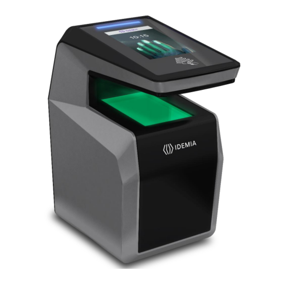
2.3 > Terminal's front view description Speaker Status LED 4.3'’ WVGA Contactless touchscreen LCD card area Microphone Hand proximity sensor Contactless biometric sensor Optional Wifi interface Figure 3: MorphoWave Compact terminal front view MorphoWave Compact - 2018_2000035853... -
Page 25: Terminal's Rear View Description
USB mass storage key, or for installation of a Wi-Fi™ USB dongle) SAM card (option) Power supply, Relay, Tamper switch GPIO RS485 / RS422 Wiegand RJ45 Figure 4: MorphoWave Compact terminal rear view MorphoWave Compact - 2018_2000035853... -
Page 26: Morphowave Compact Technical Characteristics
2.5 > MorphoWave Compact Technical Characteristics Item Description Access control modes Identification (search for fingerprints in a local database) Authentication with contactless smartcard, with or without fingerprint check Multi-factor: identification or authentication (only if terminal is equipped with a contactless smartcard reader) - Page 27 W x H x D: 152 mm x 250 mm x 220 mm (6.98” x 9.84” x 8.66”) Weight : ~ 2 kg Environmental Operating temperature: conditions -10 °C to + 55 °C (14°F to 131°F) when ECO-mode is ON MorphoWave Compact - 2018_2000035853...
- Page 28 Avoid direct exposure to sunlight or to UV lights Certification planned CE, IEC 60950-1, FCC Part 15, RSS210 - Issue 8 : 2010, RSS-102 - Issue 5 : 2015, RSS-Gen – Issue : 2014, RoHS, REACh, WEEE MorphoWave Compact - 2018_2000035853...
-
Page 29: Installation Procedure
3 / Installation procedure MorphoWave Compact - 2018_2000035853... -
Page 30: Before Proceeding To The Installation
For an optimal use the terminal must be installed in an area where the lighting conditions are controlled. Avoid direct exposure of the sensor to the sun light and ensure good ambient lighting for face detection if used. MorphoWave Compact - 2018_2000035853... -
Page 31: Installation
For UL-294 compliance, an earthed screen in the wire or around all wires to/from product is only required when the wires share space/compartment/tube with high voltage cables. Equipment from the initial package to use One (1) Terminal’s body. One (1) wall plate. MorphoWave Compact - 2018_2000035853... -
Page 32: Step By Step Procedure
Avoid direct exposure of the sensor to the sun light. Power supply from electrical source shall be switched off before starting the installation. The strength of the attachment depends on the solidity of the wall on which the terminal is mounted. MorphoWave Compact - 2018_2000035853... -
Page 33: Drill The Mounting Holes
Drill in the wall 4 holes with a diameter adapted to screws and fit them with the raw plugs (see Figure 7: Drilling template). Be sure that a sufficient space is reserved in the wall for the passage of cables, in particular for Ethernet. MorphoWave Compact - 2018_2000035853... -
Page 34: Make The Connections
3.3.2 > Make the connections Unscrew the connector from the device: Fit the cables through the mounting plate: MorphoWave Compact - 2018_2000035853... - Page 35 Cable for wiring shall be AWG 20 to 24, length shall be adapted to the size of the hole in the wall, to terminal connections, and to the distance between the electric source and the terminal itself. To ensure water tightness, be sure to bend the cable downward. MorphoWave Compact - 2018_2000035853...
-
Page 36: Attach The Base Plate On The Wall
OTHER connector on the device side. Please use only the pinout information given in this document in section 4 /. 3.3.3 > Attach the base plate on the wall Fix the base plate on the wall with the 4 screws. MorphoWave Compact - 2018_2000035853... -
Page 37: Attach The Device On The Base Plate
3.3.4 > Attach the device on the base plate MorphoWave Compact - 2018_2000035853... -
Page 38: Connect The Connector Assembly On The Device
3.3.5 > Connect the connector assembly on the device Attach the connector assembly on the device with the 4 screws. MorphoWave Compact - 2018_2000035853... -
Page 39: Close The Device On The Base Plate
! Then rotate the device 90° to align it in the final position in front of the plate. Push the device towards the wall, then downwards until the device is locked on the plate. MorphoWave Compact - 2018_2000035853... - Page 40 The hardware installation of the product on the wall is complete ! Power can be switched ON just after closing it. If the product has to be stored for a long time (more than 48 hours), don’t forget to restore its configuration before use. MorphoWave Compact - 2018_2000035853...
-
Page 41: Electrical Interface
4 / Electrical interface MorphoWave Compact - 2018_2000035853... -
Page 42: Wiring Overview
Power supply ground shall not be used for peripheral ground. All other grounds can be used indifferently. Note that all connections of the MorphoWave Compact terminal described hereafter are of SELV (Safety Electrical Low Voltage) type. Figure 9: Cabling layout... -
Page 43: Power Supply
If sharing power between devices, each unit must receive 2.5A (e.g. two units would require a 12vDC, 5A supply). IDEMIA recommends using a 24V power supply and AWG16 gauge cable. The voltage measured on the product block connector of the terminal must be equal to 12V-24V (-15% / +10%). -
Page 44: Power Supply
PoE+ (Power over Ethernet Plus) MorphoWave Compact terminal's power supply can also be provided by the Ethernet using RJ45 connection (Power over Ethernet Plus mode - IEEE802.3at type 2 compliant). The terminal may be powered via a UL 294B PSE PoE+ Limited power source with a range of 48VDC (- 10% /+15%). -
Page 45: Output Relay
The internal relay is designed for at least 100 000 cycles (resistive load). Inductive load management requires a parallel diode for a better contact lifetime. Example of connection for electrical door locks MorphoWave Compact terminal Figure 12: Example of electric latch connection MorphoWave Compact - 2018_2000035853... -
Page 46: Tamper Switch
100 mA at 30 VDC max (Resistive load) according to the safety extra low voltage standard. terminal is part of security system; it is customer’s responsibility MorphoWave Compact This to connect the tamper switch (contact) to physical access controller, in order to prevent the access to the connector blocks. MorphoWave Compact - 2018_2000035853... -
Page 47: Wiegand Wiring
If pull-up’s to 12V have been added on Wiegand IN D0 and Wiegand IN D1 inputs on a previous installation with a MorphoAccess® 500 Series terminal, these resistors must be removed to avoid any damage to the MorphoWave Compact terminal. MorphoWave Compact - 2018_2000035853... -
Page 48: Wiegand Output
LED1 and the GND wires, and it means “access granted”. The MorphoWave Compact terminal uses the timeout of the wait for a low level on the on LED1 wire or LED2 wire as “access denied” answer. - Page 49 (by closing a contact between the LED2 and the GND wires), whatever is the state of the LED1 wire. The MorphoWave Compact terminal also considers that the answer of the controller is "access denied" in case of time-out while expecting for a closure between LED1 and GND wires, or between LED2 and GND wires.
-
Page 50: Serial Port Wiring
LED IN 1 (option): panel feedback Blue WIEGAND_LEDOUT1 (Output type required: Open drain or 5V+/-5%) LED IN 2 (option): panel feedback Blue / Red WIEGAND_LEDOUT2 (Output type required: Open drain or 5V+/-5%) Black / Red WIEGAND_GND Ground for Wiegand MorphoWave Compact - 2018_2000035853... -
Page 51: Serial Port Wiring
RS422 non inverting Receive Blue / White RS485_RX_B RS422 inverting Receive Green / Black RS485_TX_Y RS422 non inverting Transmit Green / White RS485_TX_Z RS422 inverting Transmit Black / Red RS485_GND Ground RS422 interface is a full duplex communication. MorphoWave Compact - 2018_2000035853... -
Page 52: Gpio Wiring
Single Door Access Control (SDAC) implementation Push button / Motion sensor External Power GPI_0 supply Door GPO_0 strike GPI_1 GPO_1 RELAY_COM RELAY_NO/NC Door contact Figure 21: SDAC wiring If door contact is not used, GPI1 and GPO1 shall be connected together MorphoWave Compact - 2018_2000035853... -
Page 53: Ethernet Connection
MDI or MDI-X. Ethernet cable shall be shielded Ethernet interface can be used to power the MorphoWave Compact terminal through PoE+ (Power Over Ethernet Plus - IEEE802.3at type 2 mode). According to the PoE+ standard two modes are available: power on data pins and power on dedicated pins. -
Page 54: Internal Usb Connection
4.10 > Internal USB connection Remove the 4 screws of the cover, as shown on the following drawing. Then remove the cover. Then you can see a Mini USB plug. Mini USB type B connector Figure 23: Internal USB connection MorphoWave Compact - 2018_2000035853... - Page 55 The internal Mini USB-type B can be used for administration only to connect a mass storage USB key (with a standard Mini USB-type B / USB-type A female OTG adapter). This cable can be found in Idemia catalogue with ref TBD. Please refer to MorphoWave Compact Administration Guide for more information.
-
Page 56: Wi-Fi™ Dongle Installation
PoE+ doesn’t provides enough power for both the terminal and the Wi-Fi™ dongle). Only Wi-Fi™ USB dongle delivered by Idemia (kit reference 293686787, containing the dongle and the cable) may be installed with the terminal for WLAN (Wireless Local Area Network) operation. -
Page 57: Wi-Fi™ Dongle Installation
2. connect 1. connect 3. Insert the 4. Attach the cover and dongle in the hole tighten the screws Figure 24: Wi-Fi™ dongle installation Close the product with the cover and tighten the 4 screws. MorphoWave Compact - 2018_2000035853... -
Page 58: User Interface
5 / User interface MorphoWave Compact - 2018_2000035853... -
Page 59: Modes For Controlling Access Rights
5.1 > Modes for controlling access rights 5.1.1 > Introduction The MorphoWave Compact terminal offers several methods for controlling access rights: it needs to be configured in one of the following four modes: Identification mode, Authentication mode (requires a contactless smartcard reader in the terminal), ... -
Page 60: Proxy Mode
The MorphoWave Compact terminal is driven through an Ethernet (or Wi-Fi™) link using TCP, SSL or TLS protocol. The MorphoWave Compact terminal acts as a server: it is either waiting for a command or executing a command. The commands allowed by the MorphoWave Compact terminal are described in the MorphoWave Compact Host System Interface Specification document. - Page 61 MorphoWave Compact Host System Interface Specification document to know how to set this parameter. Configuring the terminal MorphoWave Compact terminals are standalone biometric systems which offers advance features for access control. MorphoWave Compact terminals are equipped with a facility to support the MorphoAccess®...
-
Page 62: Morphowave Compact Native Mode
5.1.7 > MorphoWave Compact native mode MorphoWave Compact terminal is by default in native mode, that is named MA5G. It will support the new features and configurations only in the native mode. NOTA : When terminal mode is switched from MA5G to Morpho legacy mode, the entire configuration (excepted communication links) and all databases are erased NOTA : The terminal is rebooted on mode change and factory settings are applicable. -
Page 63: Anti-Tamper / Anti-Pulling Switches
They are deactivated as soon as this pressure is not big enough, e.g. when the terminal is pulled out of the wall. When the switches are deactivated, the MorphoWave Compact terminal acts as required by the related configuration key (see MorphoWave Compact Administrator / User Guide for key configuration description): ... -
Page 64: Accessories, Software Licenses And Pc Applications
6 / Accessories, Software Licenses and PC Applications MorphoWave Compact - 2018_2000035853... -
Page 65: Compatible Accessories, Licenses And Software
6.1 > Compatible Accessories, Licenses and Software The following items can be ordered directly to Idemia or to an official distributor, so as to enjoy all the features of your MorphoWave Compact terminal: Power supply units, Contactless smartcards: MIFARE® 1k, 4k; DESFire® 2k, 4k, 8k, ... -
Page 66: Compatible Pc Applications
Morpho Integrator’s Kit (MIK) software development kit (version 6 or higher). MorphoBioToolBox (version 3.4.3 or higher) Using Legacy Morpho mode, MorphoWave Compact is also compatible with: MEMS (version 7.3.1 or higher), MIK (version 5.4 or higher), The limitations in Morpho Legacy mode are described in the following document: ... -
Page 67: Recommendations
7 / Recommendations MorphoWave Compact - 2018_2000035853... -
Page 68: Recommendations
The terminal clock has a +/-10 ppm typical time deviation at +25°C (roughly around +/- 6 sec per 48 hours). At lower and higher temperature (but within normal operating temperatures), deviation may be more important (worst case: - 14 seconds per 48 hours). MorphoWave Compact - 2018_2000035853... - Page 69 The use of acid liquids, alcohol or abrasive materials is prohibited. Use dry air spray to remove the dust out of the sensor glass. MorphoWave Compact - 2018_2000035853...
-
Page 70: Annex 1 : Finger Placement Recommendations
8 / Annex 1 : finger placement recommendations MorphoWave Compact - 2018_2000035853... -
Page 71: Main Principles
8.1 > Main principles MorphoWave Compact is a biometric acquisition terminal which captures fingerprints by the applicant waving their hand through the active volume. The product can track and capture simultaneously up to 4 fingerprints at a maximum speed of 0.5m/s. -
Page 72: Capture Recommendations
8.2 > Capture recommendations Proper Use Below are several illustrations and guidelines on how to best use your new MorphoWave Compact device. MorphoWave Compact - 2018_2000035853... -
Page 73: Improper Use
Improper Use The following illustrations show what NOT to do when using Finger on the Fly. MorphoWave Compact - 2018_2000035853... - Page 74 MorphoWave Compact - 2018_2000035853...
-
Page 75: Annex 2 : Bibliography
9 / Annex 2 : Bibliography MorphoWave Compact - 2018_2000035853... -
Page 76: How To Get The Latest Versions Of Documents
The last version of the documents can be downloaded from our web site at the address below: www.biometric-terminals.com (Login and password required). To request a login, please send us an email to the address below: hotline.biometrics@morpho.com MorphoWave Compact - 2018_2000035853... -
Page 77: Documents About The Morphowave Compact Terminal
9.2 > Documents about the MorphoWave Compact terminal Documents about installing the terminal MorphoWave Compact Installation Guide, Ref. 2018_2000035853 This document describes terminal physical mounting procedure, electrical interfaces and connection procedures. This document is in English. Documents about administrating / using the terminal MorphoWave Compact Quick User Guide, Ref. -
Page 78: Annex 3 : Support
10 / Annex 3 : Support MorphoWave Compact - 2018_2000035853... -
Page 79: Troubleshooting
North and South America: e-mailing cscenter@morpho.com with your name, phone number, product serial number and “Send Links For MorphoWave Compact Documents” in the subject line Other countries: please visit our web site www.biometric-terminals.com (To get your log in and password please contact your sales representative).
Need help?
Do you have a question about the MorphoWave Compact and is the answer not in the manual?
Questions and answers