Advertisement
Advertisement
Table of Contents

Related Manuals for IFM PK752 Series


Summary of Contents for IFM PK752 Series
- Page 1 Operating Instructions Electronic pressure monitor PK752x SET1 SET2...
- Page 2 Contents 1 Preliminary note ���������������������������������������������������������������������������������������������������2 1�1 Symbols used ������������������������������������������������������������������������������������������������2 2 Safety instructions �����������������������������������������������������������������������������������������������2 3 Function and features ������������������������������������������������������������������������������������������4 4 Installation������������������������������������������������������������������������������������������������������������4 5 Electrical connection ��������������������������������������������������������������������������������������������4 6 Setting / Operation �����������������������������������������������������������������������������������������������5 1 Preliminary note 1.1 Symbols used ► Instruction > Reaction, result […] Designation of keys, buttons or indications →...
- Page 3 2 Safety instructions • The device described is a subcomponent for integration into a system� - The manufacturer is responsible for the safety of the system� - The system manufacturer undertakes to perform a risk assessment and to create documentation in accordance with legal and normative requirements to be provided to the operator and user of the system�...
- Page 4 3 Function and features The pressure monitor detects the system pressure and generates two output signals (2 NO with independently adjustable switch points: • In case of increasing pressure OUT1 (OUT2) closes when the Set1 (Set2) value is reached� • In case of decreasing pressure OUT1 (OUT2) opens when the value „Set1 (Set2) minus hysteresis“...
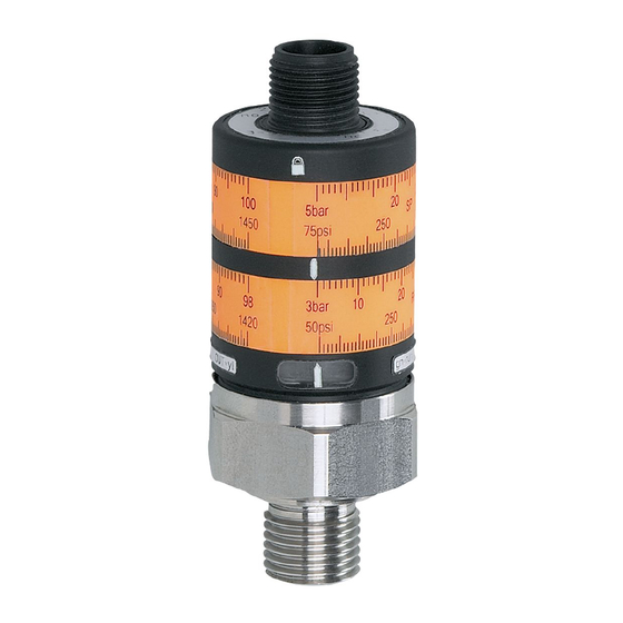
- Page 5 6: yellow LED: Set2 value reached, OUT2 = ON 7: sealing FPM / DIN 3869-14 8: internal thread M5 • To obtain the setting accuracy: Set the rings to the minimum value, then set the requested value� More information at www�ifm�com...
Need help?
Do you have a question about the PK752 Series and is the answer not in the manual?
Questions and answers