Table of Contents
Advertisement
Quick Links
Advertisement
Table of Contents

Related Manuals for IFM PI16 Series


Summary of Contents for IFM PI16 Series
- Page 1 Operating instructions Electronic pressure sensor PI16xx PI18xx...
-
Page 2: Table Of Contents
PI16xx PI18xx Electronic pressure sensor Contents Preliminary note ............. Symbols used . - Page 3 Electronic pressure sensor PI16xx PI18xx 10.4.6 Set damping for the analogue signal ........29 10.5 Service functions.
-
Page 4: Preliminary Note
PI16xx PI18xx Electronic pressure sensor 1 Preliminary note You will find instructions, technical data, approvals and further information using the QR code on the unit / packaging or at www.ifm.com. 1.1 Symbols used Requirement Instructions Reaction, result [...] Designation of keys, buttons or indications... -
Page 5: Safety Instructions
Electronic pressure sensor PI16xx PI18xx 2 Safety instructions • The unit described is a subcomponent for integration into a system. – The system architect is responsible for the safety of the system. – The system architect undertakes to perform a risk assessment and to create documentation in accordance with legal and normative requirements to be provided to the operator and user of the system. -
Page 6: Intended Use
PI16xx PI18xx Electronic pressure sensor 3 Intended use The device measures and monitors the system pressure or the hydrostatic level and the temperature in systems. 3.1 Application area Type of pressure: relative pressure Information on pressure rating and bursting pressure Ò Data sheet Avoid static and dynamic overpressure exceeding the indicated pressure rating by taking appropriate measures. -
Page 7: Function
Detection of connected units. • Freely definable parameters to identify the units in the plant. Information and documentation on the IO-Link interface at: www.io-link.ifm 4.2 IO-Link properties of the sensor 4.2.1 Description IO-Link interface A description of the IO-Link interface can be found at... -
Page 8: Internal Unit Temperature
PI16xx PI18xx Electronic pressure sensor The sensor provides the internal unit temperature as a readable parameter for diagnostic purposes. 4.2.2 Internal unit temperature The internal temperature of the sensor can be read via the IO-Link channel. Measuring range: -25...155°C (-13...311°F), resolution 1°C (1.8°F), precision +/- 5°C (9°F). Information on measuring range and accuracy Ò... -
Page 9: Defined State In Case Of A Fault
Electronic pressure sensor PI16xx PI18xx 4.3 Defined state in case of a fault If a fault is detected, the analogue output passes into a defined state ( = 21.5 mA). In case of a fault indication ( = 21.5 mA) u Read parameters via IO-Link or contact the manufacturer. 4.4 Operating modes The operating mode is defined by the wiring (Ò... -
Page 10: Analogue Output
PI16xx PI18xx Electronic pressure sensor System pressure HY = Hysteresis FE = Window 4.6 Analogue output The device provides an analogue signal proportional to the pressure. Within the measuring range the analogue signal is between 4...20 mA. The measuring range is scalable: •... - Page 11 Electronic pressure sensor PI16xx PI18xx u Carry out calibration factor [CGA] in the range -5%..+5% of final value of the measuring range (VMR). The previous zero point calibration remains. Example: Change zero point [coF] Output signal Pressure 105 % MEW MEW: Final value of the measuring range 100 % MEW Curve of measured values at factory setting...
-
Page 12: Installation G1 Sealing Cone (Pi16Xx)
Note dangers related to machine / medium temperatures. Information about available adapters at: www.ifm.com u Observe the instructions of the adapter. u Use a lubricating paste which is suitable and approved for the application. -
Page 13: Use In Hygienic Areas According To 3-A
Electronic pressure sensor PI16xx PI18xx 5.1 Use in hygienic areas according to 3-A The following applies to units with 3-A certification: u Only use adapters with A-3 certification for the process connection. u Do not install the unit at the lowest point of the pipe or tank (position 5) so that the medium can run off the area of the measuring element. -
Page 14: Installation G1 Sealing Cone With Coupling Nut (Pi18Xx)
Note dangers related to machine / medium temperatures. The unit must only be installed in an ifm process connection with G1 sealing cone designed for this. Information about available adapters at: www.ifm.com... -
Page 15: Use In Hygienic Areas According To 3-A
Electronic pressure sensor PI16xx PI18xx An elastomer-free seal in chemical applications is possible with a metal-to-metal seal. u For hygienic applications, avoid repeated installation to avoid compromising the sealing effect. A guarantee for a long-term stable sealing effect only exists with one-time installation. Use of welding adapters: u During the welding process, make sure that the adapter is not deformed and that the sealing edge is not affected. -
Page 16: Orientation Filter Cover
PI16xx PI18xx Electronic pressure sensor 6.3.2 Orientation filter cover Select the installation situation so that the filter cover is horizontal and the condensate can drain off due to gravity. u Ideal orientation (1): The filter cover is in a horizontal position. w The ventilation diaphragm (2) in the filter cover is in a vertical position. - Page 17 Electronic pressure sensor PI16xx PI18xx • Fluctuations in the internal pressure of the unit with temperature changes.
-
Page 18: Electrical Connection
PI16xx PI18xx Electronic pressure sensor 7 Electrical connection The unit must be connected by a qualified electrician. The national and international regulations for the installation of electrical equipment must be adhered to. The circuit of the unit is isolated from touchable parts by functional insulation. Supply voltage SELV, PELV according to the technical data sheet. -
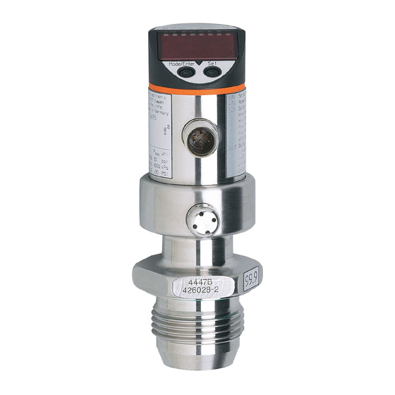
Page 19: Operating And Display Elements
Electronic pressure sensor PI16xx PI18xx 8 Operating and display elements 1 to 8: Indicator LEDs LED 1 - 6 Unit of measurement of the process value pressure (assignment is device-specific). LED 7 Switching status OUT2 (on if output 2 is switched). LED 8 Switching status OUT1 (on if output 1 is switched). -
Page 20: Menu
PI16xx PI18xx Electronic pressure sensor 9 Menu 9.1 Menu structure: Main menu 9.05 1000 1000 1000 1000 ASP2 AEP2 1000 ..tcoF tASP ..tAEP 1: Change to menu level 2 (extended functions). Menu items highlighted in grey are active depending on the configuration of the output. 9.2 Explanation of the main menu SPx / rPx* Hysteresis function: upper / lower limit value for system pressure at which OUTx switches. -
Page 21: Menu Structure: Level 2 (Extended Functions)
Electronic pressure sensor PI16xx PI18xx 9.3 Menu structure: Level 2 (extended functions) APPL Hi.P 0.00 Lo.P FOU1 FOU2 0.06 0.03 0.00 uni.P 1: Change to the main menu, 2: Change to menu level 3 (simulation). Menu items highlighted in grey are not active in 2-wire operation. 9.4 Explanation of menu level 2 Restore the factory settings. -
Page 22: Menu Structure: Level 3 (Simulation)
PI16xx PI18xx Electronic pressure sensor Adjustment of final value of the measuring range between: -5%...+5% of VMR. Update rate and orientation of the display Open the submenu SIM (simulation) * menu items not active in 2-wire operation ** Time constant tau 9.5 Menu structure: level 3 (simulation) ---- S.PRS... -
Page 23: Parameter Setting
Electronic pressure sensor PI16xx PI18xx 10 Parameter setting During parameter setting the unit remains in the operating mode. It continues its monitoring functions with the existing parameters until the parameter setting has been completed. 10.1 Parameter setting in general 3 steps must be taken for each parameter setting: 1: Select Parameter u Press [Enter] to get to the menu. - Page 24 PI16xx PI18xx Electronic pressure sensor u Briefly press [Enter]. w The parameter is displayed again. The new setting value is saved. Setting of other parameters: u Press [▲] or [▼] until the required parameter is displayed. Finishing the parameter setting: u Press [▲] or [▼] several times until the current measured value is displayed or wait for 30 s.
- Page 25 Electronic pressure sensor PI16xx PI18xx u Press [Enter]. w The first parameter of the submenu is displayed (here: [rES]). w Continue with [▼]. Lock / unlock The unit can be locked electronically to prevent unintentional settings. Locking: 10 s u Make sure that the unit is in normal operating mode. u Press [▲] + [▼] simultaneously for 10 s.
-
Page 26: Configure Display (Optional)
PI16xx PI18xx Electronic pressure sensor Exit parameter without applying the settings: u Press [▲] + [▼] simultaneously. w Return to the menu level. To exit the menu level: u Press [▲] + [▼] simultaneously. w Menu level 2 changes to level 1 level 1 changes to the display. -
Page 27: Set Output Signals
Electronic pressure sensor PI16xx PI18xx u Select [diS] and set the update rate and orientation of the display: [diS] • [d1]: update of the measured values every 50 ms. • [d2]: update of the measured values every 200 ms. • [d3]: update of the measured values every 600 ms. •... -
Page 28: User Settings (Optional)
PI16xx PI18xx Electronic pressure sensor u Approach the desired maximum system pressure in the installation and keep it constant. [tAEP] u Select [tAEP] with [Enter]. u Press [▲] or [▼] until [----] is displayed. u Confirm [----] with [Enter]. w The current system pressure is defined as end value for the analogue signal. ASP / AEP can only be set within defined limits (Ò... -
Page 29: Set Damping For The Switching Signal
Electronic pressure sensor PI16xx PI18xx 10.4.5 Set damping for the switching signal u Select [dAP] and set a value between 0.00...99.99 s; (at 0.00 [dAP] is not active). [dAP] dAP value = response time between pressure change and change of the switching status in seconds. [dAP] influences the switching frequency: f = 1 ÷... -
Page 30: Simulation Function
PI16xx PI18xx Electronic pressure sensor After the reset, the sensor suspends communication and measurement operation until the voltage is interrupted. The IO-Link data storage is not triggered. 10.6 Simulation function 10.6.1 Open menu level 3 (simulation) u Select the parameter [SIM] in menu level 2 (extended functions) with [▲] or [▼]. [SIM] u Press [Enter] (= open menu level 3). -
Page 31: Read Overload Processes
Electronic pressure sensor PI16xx PI18xx 10.7.4 Read overload processes • HIPC: Number of overload processes. [HIPC] HIPC counts how often the limit HIPS has been exceeded. [HIPS] The limit must be exceeded for at least 0.5 ms. • HIPS: Setting of the threshold for the overload counter. The parameters HIPC and HIPS are only available via IO-Link communication. -
Page 32: Operation
PI16xx PI18xx Electronic pressure sensor 11 Operation After power-on and expiry of the power-on delay time of approx. 0.5 s the unit is in the RUN mode (= normal operating mode). It carries out its measurement and evaluation functions and generates output signals according to the set parameters. -
Page 33: Troubleshooting
Electronic pressure sensor PI16xx PI18xx 12 Troubleshooting 12.1 Troubleshooting The unit has many self-diagnostic options. • It monitors itself automatically during operation. • It indicates warnings and faults via IO-Link and via display (even if the display is deactivated). • If a fault is found, the outputs are set according to the setting of the parameters FOU1 and FOU2. Display Warning Error... -
Page 34: Disposal, Repair And Return
PI16xx PI18xx Electronic pressure sensor 13 Disposal, repair and return u After use dispose of the unit in an environmentally friendly way in accordance with the applicable national regulations. u In case of return shipment, ensure that the unit is free from soiling, especially from dangerous and toxic substances. -
Page 35: Factory Setting
Electronic pressure sensor PI16xx PI18xx 14 Factory setting Factory setting User settings 25% VMR * 23% VMR * 75% VMR * 73% VMR * coF / tcoF ASP / tASP 0% VMR * PI1x09: -1 bar AEP / tAEP 100% VMR * bAr / mbAr FOU1 FOU2...
Need help?
Do you have a question about the PI16 Series and is the answer not in the manual?
Questions and answers