Table of Contents
Advertisement
Quick Links
Advertisement
Table of Contents

Related Manuals for IFM PF295 Series


Summary of Contents for IFM PF295 Series
- Page 1 Operating instructions Electronic pressure sensor PF295x...
-
Page 2: Table Of Contents
Contents 1 Preliminary note ���������������������������������������������������������������������������������������������������3 1�1 Symbols used ������������������������������������������������������������������������������������������������3 2 Safety instructions �����������������������������������������������������������������������������������������������3 3 Functions and features ����������������������������������������������������������������������������������������4 3�1 Applications ���������������������������������������������������������������������������������������������������4 4 Function ���������������������������������������������������������������������������������������������������������������4 4�1 Processing of the measured signals ��������������������������������������������������������������4 4�2 Pressure monitoring / switching function �������������������������������������������������������5 4�3 Pressure monitoring/ analogue function ��������������������������������������������������������5 5 Installation������������������������������������������������������������������������������������������������������������7 6 Electrical connection ��������������������������������������������������������������������������������������������9 7 Operating and display elements ������������������������������������������������������������������������10... -
Page 3: Preliminary Note
10�1 Read the set parameter values �����������������������������������������������������������������17 10�2 Fault indication ������������������������������������������������������������������������������������������17 10�3 Cleaning of the filter cover �������������������������������������������������������������������������17 1 Preliminary note 1.1 Symbols used ► Instruction > Reaction, result […] Designation of buttons, switches or indications → Cross-reference Important note Non-compliance can result in malfunctions or interference�... -
Page 4: Functions And Features
• Installation, electrical connection, set-up, programming, configuration, operation and maintenance of the product must be carried out by personnel qualified and authorised for the respective activity� • Protect units and cables against damage� 3 Functions and features The pressure sensor detects the system pressure of machines and installations� 3.1 Applications Type of pressure: relative pressure Information on pressure rating and bursting pressure →... -
Page 5: 4�2 Pressure Monitoring / Switching Function
4.2 Pressure monitoring / switching function OUTx changes its switching state if it is above or below the set switching limits (SPx, rPx)� The following switching functions can be selected: • Hysteresis function / normally open: [OUx] = [Hno] (→ fig. 1). •... - Page 6 Current output Factory setting Measuring range scaled I [mA] I [mA] P = system pressure, MEW = final value of the measuring range The output signal is between 4 and 20 mA� It is also indicated: • System pressure above the measuring range: output signal > 20 mA � •...
-
Page 7: Installation
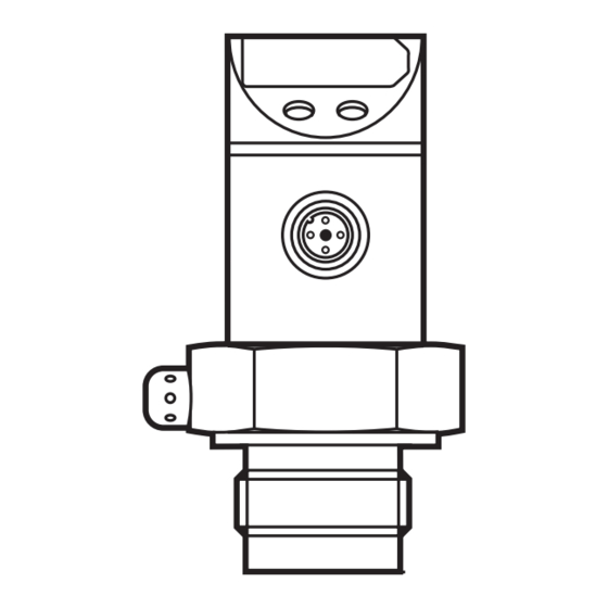
5 Installation Ensure that no pressure is applied to the installation while mounting or removing the sensor� ► Screw the sensor into a G¾ process fitting� ► Tighten the sensor with a spanner until you can feel the end stop� You can replace the Viton O-ring (B) by the supplied EPDM O-ring�... - Page 8 Mounting the adapter ► Slightly grease the threads and sealing areas of the sensor and adapter with lubricating paste (1)� The paste must be suitable and approved for the application and compatible with the elastomers used� Recommendation: Klüber paste UH1 84-201 with USDA-H1 approval for the food industry�...
-
Page 9: Electrical Connection
1 x p-switching / 1 x analogue 1 x n-switching / 1 x analogue 2: OUT2 2: OUT2 4: OUT1 4: OUT1 Core colours of ifm sockets: 1 = BN (brown), 2 = WH (white), 3 = BU (blue), 4 = BK (black) -
Page 10: Operating And Display Elements
7 Operating and display elements Mode/Enter 1: 7-segment display - Display of the system pressure - display of parameters and parameter values� 2: 2 x LED red - Switching status; lights if output I / II has switched� 3: Set button - Setting of the parameter values (scrolling by holding pressed;... -
Page 11: Menu
8 Menu 8.1 Menu structure OU2 = Hno, Hnc, Fno, Fnc OU2 = I, U... -
Page 12: 8�2 Menu Explanation
8.2 Menu explanation SP1/rP1 Maximum / minimum value for system pressure, at which output 1 changes its switching status� Output function for OUT1: • Switching signal for the limit values: hysteresis function [H ��] or window function [F ��], normally open [� no] or normally closed [� nc] each� Output function for OUT2: •... -
Page 13: Parameter Setting
9 Parameter setting During the parameter setting process the unit remains in the operating mode� It continues its monitoring function with the existing parameters until parameter setting has been terminated� 9.1 Parameter setting general Each parameter setting requires 3 steps: Selecting parameter ►... -
Page 14: 9�2 Configuring The Display (Optional)
• Changing from menu level 1 to menu level 2 � ► Press [Mode/Enter] until [EF] is displayed. ► Press [Set] briefly� > The first parameter of the submenu is displayed (here: [HI])� • Locking / unlocking The unit can be locked electronically to prevent unintentional wrong settings� ►... -
Page 15: 9�3 Setting The Output Signal
9.3 Setting the output signal 9.3.1 Setting the output function ► Select [OU1] and set the switching function: - [Hno] = hysteresis function / normally open, - [Hnc] = hysteresis function / normally closed, - [Fno] = window function / normally open, - [Fnc] = window function / normally closed�... -
Page 16: 9�4�3 Setting The Delay Time For The Switching Outputs
9.4.3 Setting the delay time for the switching outputs [dS1] / [dS2] = switch-on delay for OUT1 / OUT2� [dr1] / [dr2] = switch-off delay for OUT1 / OUT2� ► Select [dS1], [dS2], [dr1] or [dr2], set value between 0�1 und 50 s (at 0�0 the delay time is not active) 9.4.4 Setting the output polarity ►... - Page 17 The vent (A) should only be cleaned by skilled personnel and with utmost care� Possible medium residues must not be compressed and pressed into the vent� This could clog the filter system and reduce the measuring accuracy of the sensor� ► Screw the filter cover again tightly� More information at www�ifm�com...
Need help?
Do you have a question about the PF295 Series and is the answer not in the manual?
Questions and answers