Table of Contents
Advertisement
Quick Links
Advertisement
Table of Contents

Subscribe to Our Youtube Channel
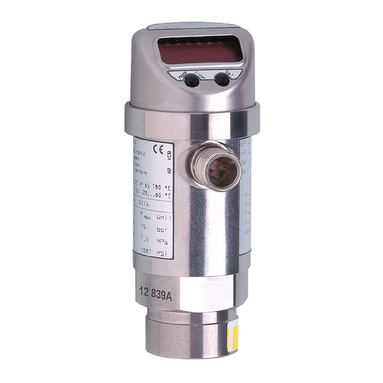
Summary of Contents for IFM PN01 A Series
- Page 1 Operating instructions Pressure sensor PN01xA...
-
Page 2: Table Of Contents
Contents 1 Preliminary note ���������������������������������������������������������������������������������������������������3 1�1 Symbols used ������������������������������������������������������������������������������������������������3 2 Safety instructions �����������������������������������������������������������������������������������������������3 3 Functions and features ����������������������������������������������������������������������������������������4 4 Function ���������������������������������������������������������������������������������������������������������������4 4�1 Communication, parameter setting, evaluation ���������������������������������������������4 4�2 Switching function ������������������������������������������������������������������������������������������5 4�3 Diagnostic function ����������������������������������������������������������������������������������������5 5 Installation������������������������������������������������������������������������������������������������������������6 6 Electrical connection ��������������������������������������������������������������������������������������������6 7 Operating and display elements ��������������������������������������������������������������������������7 8 Menu ��������������������������������������������������������������������������������������������������������������������8 8�1 Menu structure �����������������������������������������������������������������������������������������������8... -
Page 3: Preliminary Note
11 Scale drawing ��������������������������������������������������������������������������������������������������15 12 Technical data ��������������������������������������������������������������������������������������������������15 13 Factory setting �������������������������������������������������������������������������������������������������17 1 Preliminary note 1.1 Symbols used ► Instruction > Reaction, result […] Designation of pushbuttons, buttons or indications → Cross-reference Important note Non-compliance can result in malfunction or interference� Information_Supplementary note�... -
Page 4: Functions And Features
• The following functions are available via IO-Link (OUT1): Reading the current process value, changing parameters and transferring them to other units of the same type using the FDT service program ifm Container or other parameter setting tools with IO-Link capability. The program library of the available DTM objects and the IO Device Description (IODD) are available at www.ifm.com →... -
Page 5: 4�2 Switching Function
4.2 Switching function OUTx changes its switching state if it is above or below the set switching limits (SPx, rPx). The following switching functions can be selected: • Hysteresis function / normally open: [OUx] = [Hno] (→ fig. 1). • Hysteresis function / normally closed: [OUx] = [Hnc] (→ fig. 1). First the set point (SPx) is set, then the reset point (rPx) with the requested difference�... -
Page 6: Installation
• Binary switching output if [OU2] = [Hno], [Hnc], [Fno] or [Fnc] Pin 2 (OUT2) • Diagnostic output if [OU2] = [dESI] Core colours of ifm sockets: 1 = BN (brown), 2 = WH (white), 3 = BU (blue), 4 = BK (black) -
Page 7: Operating And Display Elements
7 Operating and display elements 3 4 5 6 Mode/Enter 1 to 8: indicator LEDs - LED 1 to LED 3 = system pressure in the unit of measurement which is indicated on the label� - LEDs 4 - 6 not used� - LED 7, LED 8 = switching state of the corresponding output�... -
Page 8: Menu
8 Menu 8.1 Menu structure... -
Page 9: 8�2 Explanation Of The Menu
8.2 Explanation of the menu SP1/rP1 Upper / lower limit value for system pressure at which OUT1 switches. SP2/rP2 Upper / lower limit value for system pressure at which OUT2 switches. Output function for OUT1: • Switching signal for the pressure limit values: hysteresis function [H ��] or window function [F ��], either normally open [�... -
Page 10: Parameter Setting
9 Parameter setting During parameter setting the unit remains in the operating mode� It continues its monitoring functions with the existing parameters until the parameter setting has been completed� 9.1 Parameter setting in general 3 steps must be taken for each parameter setting: Select parameter ►... - Page 11 > The first parameter of the submenu is Mode/Enter Set displayed (here: [Uni])� With the user interface of the program ifm Container: ► Activate the [EF] button� If menu level 2 is protected by an access code, the input field for the code no� is activated�...
-
Page 12: 9�2 Configure Display (Optional)
• Timeout: If no button is pressed for 15 s during parameter setting, the unit returns to the operating mode with unchanged values� 9.2 Configure display (optional) ► Select [Uni] and set the unit of measurement: [bar], [mbar], [MPa], [kPa], [PSI]� ►... -
Page 13: 9�4 User Settings (Optional)
9.4 User settings (optional) 9.4.1 Set delay for the switching outputs [dS1] / [dS2] = switch-on delay for OUT1 / OUT2. [dr1] / [dr2] = switch-off delay for OUT1 / OUT2. ► Select [dS1], [dS2], [dr1] or [dr2] and set a value between 0�2 and 50 s (at 0�0 the delay time is not active)�... -
Page 14: Operation
10 Operation After power on, the unit is in the Run mode (= normal operating mode)� It carries out its measurement and evaluation functions and provides output signals according to the set parameters� Information on the operation indications: → chapter 7 Operating and display elements�... - Page 15 11 Scale drawing 50,5 21,5 Dimensions in mm 1: Display 2: LEDs 3: Programming button 12 Technical data Operating voltage [V] ����������������������������������������������������������������������������������������� 18���36 DC Current consumption [mA] ��������������������������������������������������������������������������������������������� < 50 Current rating per switching output [mA] ������������������������������������������������������������������������ 250 Reverse polarity / overload protection ����������������������������������������������������������������� up to 40 V Short-circuit protection;...
- Page 16 Communication interface ������������������������������������������������������������������������������������ IO-Link 1�1 Baud rate [kBAUD] ���������������������������������������������������������������������������������������������������������38�4 Accuracy / deviations (in % of the span) - Switch point accuracy �������������������������������������������������������������������������������������������� < ± 0�5 - Linearity error ��������������������������������������������������������������������� < ± 0�25 (BFSL) / < ± 0�5 (LS) - Hysteresis ���������������������������������������������������������������������������������������������������������������� < 0�25 - Repeatability (in case of temperature fluctuations <...
- Page 17 * = the indicated percentage of the final value of the measuring range (VMR) of the respective sensor (for PN014 the percentage of the measuring span) is set in bar / mbar� Technical data and further information at www.ifm.com → Select your country → Data sheet search...


Need help?
Do you have a question about the PN01 A Series and is the answer not in the manual?
Questions and answers