Table of Contents
Advertisement
Quick Links
Advertisement
Table of Contents

Related Manuals for IFM PI109 Series


Summary of Contents for IFM PI109 Series
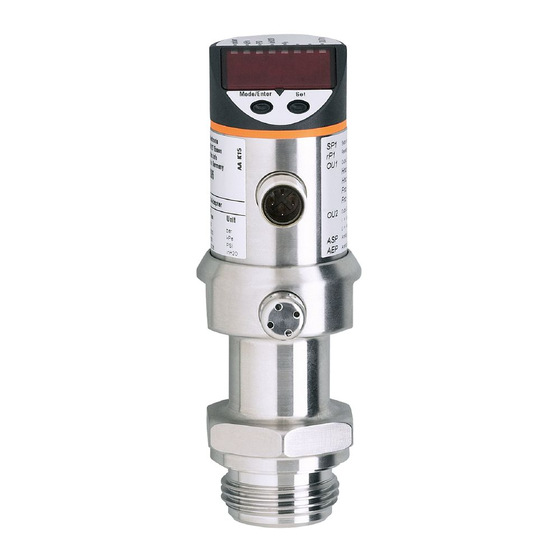
- Page 1 Operating instructions Electronic pressure sensor PI109x...
-
Page 2: Table Of Contents
Contents 1 Preliminary note ���������������������������������������������������������������������������������������������������3 1�1 Symbols used ������������������������������������������������������������������������������������������������3 2 Safety instructions �����������������������������������������������������������������������������������������������3 3 Functions and features ����������������������������������������������������������������������������������������4 3�1 Applications ���������������������������������������������������������������������������������������������������4 4 Function ���������������������������������������������������������������������������������������������������������������4 4�1 Processing of the measured signals ��������������������������������������������������������������4 4�2 Pressure monitoring/ analogue function ��������������������������������������������������������4 5 Installation������������������������������������������������������������������������������������������������������������6 6 Electrical connection ��������������������������������������������������������������������������������������������8 7 Operating and display elements ��������������������������������������������������������������������������9 8 Menu ������������������������������������������������������������������������������������������������������������������10 8�1 Menu structure ���������������������������������������������������������������������������������������������10... -
Page 3: Preliminary Note
1 Preliminary note 1.1 Symbols used ► Instruction > Reaction, result […] Designation of buttons, switches or indications → Cross-reference Important note Non-compliance can result in malfunctions or interference� 2 Safety instructions • The device described is a subcomponent for integration into a system� - The manufacturer is responsible for the safety of the system�... -
Page 4: Functions And Features
3 Functions and features The pressure sensor detects the system pressure of machines and installations� 3.1 Applications Type of pressure: relative pressure Information on pressure rating and bursting pressure → data sheet. Static and dynamic overpressures exceeding the indicated overload pressure are to be avoided by taking appropriate measures�... - Page 5 Factory setting Measuring range scaled I [mA] I [mA] P = system pressure, MAW = initial value of the measuring range, MEW = final value of the measuring range : [OU2] = [I]; : [OU2] = [InEG] The output signal is between 4 and 20 mA ([OU2] = [I]) or between 20 and 4 mA ([OU2] = [InEG])�...
-
Page 6: Installation
5 Installation Ensure that no pressure is applied to the installation while mounting or removing the sensor� Please note: Display „0%“ does not mean that the system is free of pressure! Horizontal mounting recommended for high medium temperatures� Aseptoflex adapters ensure that the sensor can be connected to different process connections�... - Page 7 Mounting the Aseptoflex adapter ► Slightly grease the threads and sealing areas of the sensor and adapter with lubricating paste (D)� The paste must be suitable and approved for the application and compatible with the elastomers used� Recommendation: Klüber paste UH1 84-201 with USDA-H1 approval for the food industry�...
-
Page 8: Electrical Connection
Pin 4 (P) P = communication via EPS / FDT interface Pin 2 (OUT2) analogue output for system pressure Core colours of ifm sockets: 1 = BN (brown), 2 = WH (white), 3 = BU (blue), 4 = BK (black) -
Page 9: Operating And Display Elements
7 Operating and display elements 3 4 5 6 Mode/Enter 1 to 8: Indicator LEDs - LED 1 to LED 6 = system pressure in unit of measurement as indicated on the label� LEDs 5 to 6 not used for units with 3 adjustable units of measurement� - LED 7 not used�... -
Page 10: Menu
8 Menu 8.1 Menu structure... -
Page 11: 8�2 Menu Explanation
8.2 Menu explanation Output function for OUT2: • Analogue signal for the current system pressure: 4���20 mA [I] or 20���4 mA [InEG]� tCOF Teaching zero-point calibration� tASP Teaching analogue start point for the system pressure: set value at which 4 mA are output (20 mA on [OU2] = [InEG])�... -
Page 12: Parameter Setting
9 Parameter setting During the parameter setting process the unit remains in the operating mode� It continues its monitoring function with the existing parameters until parameter setting has been terminated� 9.1 Parameter setting general Each parameter setting requires 3 steps: Selecting parameter ►... - Page 13 ► Press [Set] and keep it pressed until the valid code no� is displayed� ► Press [Mode/Enter] briefly� Delivery by ifm electronic: no access restriction� • Locking / unlocking The unit can be locked electronically to prevent unintentional wrong settings�...
-
Page 14: 9�2 Configuring The Display (Optional)
9.2 Configuring the display (optional) ► Select [Uni] and set the unit of measurement: - [bAr], [mbAr], - [MPA], [kPA], - [PSI], - [InHO] (only PI1096, PI1097, PI1098, PI1099), - [mWS] (only PI1096, PI1097, PI1099), - [mmWS] (only PI1098)� ► Select [SELd] and set the display mode: - [P]: Pressure in the unit set in Uni�... -
Page 15: 9�3�2 Scaling The Analogue Value
9.3.2 Scaling the analogue value ► Set the requested minimum pressure in the system� ► Press [Mode/Enter] until [tASP] is displayed� ► Press [Set] and keep the buton pressed� > The currently set value flashes� ► Release [Set] when the display stops flashing� >... -
Page 16: 9�4 User Settings (Optional)
9.4 User settings (optional) 9.4.1 Zero-point calibration ► Select [COF] and set a value between -5% and 5% of the final value of the measuring range� The internal measured value “0” is shifted by this amount� As an alternative: Automatic adaptation offset (setting range 0 bar ±5%); e�g� in the event of a deviation of the mounting location of the sensor and the zero point level for level measurement�... -
Page 17: Operation
10 Operation After power on of the supply voltage the unit is in the Run mode (= normal operation)� It carries out its measurement and evaluation functions and generates output signals according to the set parameters� Operation indication → chapter 7 Operating and display elements. 10.1 Read the set parameter values ►... -
Page 18: Factory Setting
AEP / tAEP 100% VMR* COF / tCOF bAr / mbAr SELd * = the indicated percentage of the final value of the measuring range (VMR) of the corresponding sensor in bar / mbar is set� More information at www�ifm�com...
Need help?
Do you have a question about the PI109 Series and is the answer not in the manual?
Questions and answers