Table of Contents
Advertisement
Advertisement
Table of Contents

Related Manuals for IFM PI28 Series


Summary of Contents for IFM PI28 Series
- Page 1 Operating instructions Electronic pressure sensor PI28xx...
-
Page 2: Table Of Contents
Contents 1 Preliminary note ....................4 1.1 Symbols used ....................4 2 Safety instructions ....................4 3 Functions and features ..................5 3.1 Applications ....................5 4 Function .......................6 4.1 Operating modes ...................6 4.1.1 2-wire operation ..................6 4.1.2 3-wire operation ..................6 4.2 Switching function (only for 3-wire operation) ..........7 4.3 Analogue function ..................7 4.4 Customer-specific calibration ................8 5 Installation......................10... - Page 3 9.4.2 Set output status in fault condition ............24 9.4.3 Set delay for the switching outputs .............25 9.4.4 Set output logic for the switching outputs ...........25 9.4.5 Set damping for the switching signal ..........25 9.4.6 Set damping for the analogue signal ..........25 9.4.7 Calibrate curve of measured values ...........25 9.5 Service functions ..................26 9.5.1 Read min/max values for the system pressure ........26...
-
Page 4: Preliminary Note
1 Preliminary note 1.1 Symbols used ► Instructions > Reaction, result […] Designation of keys, buttons or indications → Cross-reference Important note Non-compliance may result in malfunction or interference. Information Supplementary note. 2 Safety instructions • Read this document before setting up the product and keep it during the entire service life. -
Page 5: Functions And Features
3 Functions and features The unit measures and monitors the system pressure in a plant. 3.1 Applications Type of pressure: relative pressure Permissible Bursting Order no. Measuring range overload pressure pressure PI2893 -1...25 -14.4...362.7 1450 5075 PI2814 -1...16 -14.6...232 1085 3625 PI2894 -1...10... -
Page 6: Function
- Remote parameter setting: reading and changing the current parameter setting. - Using the FDT service program ifm Container, the current parameter settings can be stored and transferred to other units of the same type. The program library of the available DTM objects can be found at: www.ifm.com. -
Page 7: Switching Function (Only For 3-Wire Operation)
4.2 Switching function (only for 3-wire operation) OUTx changes its switching status if it is above or below the set switching limits (SPx, rPx). The following switching functions can be selected: • Hysteresis function / normally open: [OUx] = [Hno] (→ fig. 1). •... -
Page 8: Customer-Specific Calibration
Factory setting Measuring range scaled I [mA] I [mA] P = system pressure , MAW = initial value of the measuring range, MEW = final value of the measuring range : [OU2] = [I]; : [OU2] = [InEG] In the set measuring range the output signal is between 4 and 20 mA ([OU2] = [I]) or between 20 and 4 mA ([OU2] = [InEG]). - Page 9 • P = measured pressure; P‘ = modified measured value • CP1 = calibration point 1; CP1‘ = modified measured value for • CP2 = calibration point 2; CP1' • 1 = curve of measured values at factory setting • 2 = curve of measured values after calibration •...
-
Page 10: Installation
The unit must only be installed in a process connection for G1 sealing cones (e.g. ifm welding adapter, order no. E30013). If the unit is installed in a 1“ thread without a G1 sealing cone, this will lead to seal failure. -
Page 11: Filter Cover
5.1 Filter cover For particularly rough operating conditions, the sensor protection can be improved by using ifm accessories. • The filter cover can be replaced with a cover cap with a tube fitting and a vent tube that ends in a protected and dry area. -
Page 12: Connection For 2-Wire Operation
6.1 Connection for 2-wire operation Core colours brown white OUT: analogue output 4...20 mA Colours to DIN EN 60947-5-2 6.2 Connection for 3-wire operation Core colours black OUT2 brown OUT1 blue white OUT1: switching output or IO-Link OUT2: switching outputs or analogue output Colours to DIN EN 60947-5-2 Wiring example EPS Source... -
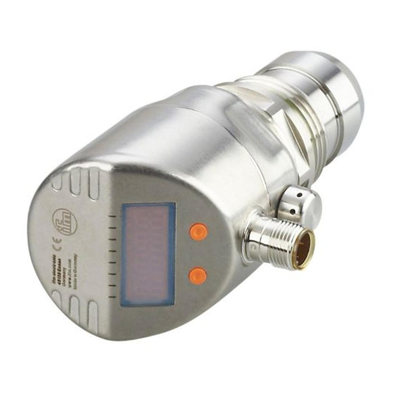
Page 13: Operating And Display Elements
If analogue signal current (I) is selected in the menu under OU2 and the output is not connected (resistor = infinite), the error message W532 is displayed in intervals. The measuring result is not affected by this. ► Alternatively: change OU2 to switching output. 7 Operating and display elements 1 2 3 4 5 6 7 8 Mode/Enter Set... -
Page 14: Menu
8 Menu 8.1 Menu structure: main menu 1: Change to menu level 2 (extended functions) Menu items highlighted grey ( SP1 ) are not active in 2-wire operation. -
Page 15: Explanation Of The Main Menu
8.2 Explanation of the main menu SP1/rP1* Upper / lower limit value for system pressure at which OUT1 switches. OU1* Output function for OUT1: • Switching signal for the pressure limit values: hysteresis function [H ..] or window function [F ..], either normally open [. no] or normally closed [. nc]. Output function for OUT2: •... -
Page 16: Menu Structure: Level 2 (Extended Functions)
8.3 Menu structure: level 2 (extended functions) 1: Change to the main menu; 2: Change to menu level 3 (simulation). Menu items highlighted grey ( ASP ) are not active in 2-wire operation. -
Page 17: Explanation Of The Menu Level 2
8.4 Explanation of the menu level 2 Standard unit of measurement for system pressure. Display mode: SELd • Pressure in the unit set in [Uni]. • Pressure in % of the set scaling of the analogue output. Analogue start point for system pressure: measured value at which 4 mA is provided (20 mA if [OU2] = [InEG]). -
Page 18: Menu Structure: Level 3 (Simulation)
8.5 Menu structure: level 3 (simulation) For setting SEL = OU 1...60 min For setting SEL = Proc 1...60 min 2: Change to menu level 2 (extended functions) Menu items highlighted grey ( S.OU1 ) are not active in 2-wire operation. -
Page 19: Explanation Of The Menu Level 3
8.6 Explanation of the menu level 3 For setting SEL = OU Status to be simulated: • Output functions [OU]. S.OU1* Simulation values for OUT1; only active for 3-wire operation and if [SEL] = [OU]. • Output inactive [OPEN] or output active [CLOS]. S.OU2 Simulation values for OUT2;... -
Page 20: Parameter Setting
Mode/Enter Set ► Press and hold [Set] until the valid code no. is displayed. ► Briefly press [Mode/Enter]. When delivered by ifm electronic: no access restriction. Set parameter value ► Press and hold [Set]. > Current setting value of the Mode/Enter Set parameter flashes for 5 s. - Page 21 This locking can only be removed with a parameter setting software. • When parameter setting is done with the user interface of the ifm Container program, the values can be directly entered in the specified fields.
-
Page 22: Configure Display (Optional)
On delivery: not locked. • Timeout: If no button is pressed for 15 s during parameter setting, the unit returns to the operating mode with unchanged values. 9.2 Configure display (optional) ► Select [Uni] and set the unit of measurement: - [bAr], [mbAr]. -
Page 23: Set Switching Limits
► Select [OU2] and set the function: - [Hno] = hysteresis function/NO, - [Hnc] = hysteresis function/NC, - [Fno] = window function/NO, - [Fnc] = window function/NC. - [I] = current signal proportional to pressure 4…20 mA. - [InEG] = current signal proportional to pressure 20…4 mA. 9.3.2 Set switching limits ►... -
Page 24: User Settings (Optional)
As an alternative: ► Select [ASP] and set the measured value at which 4 mA is provided (20 mA at [OU2] = [InEG]). ► Select [AEP] and set the measured value at which 20 mA is provided (4 mA at [OU2] = [InEG]). Minimum distance between ASP and AEP = 25 % of the final value of the measuring range (turn-down 1:4). -
Page 25: Set Delay For The Switching Outputs
9.4.3 Set delay for the switching outputs [dS1] / [dS2] = switch-on delay for OUT1 / OUT2. [dr1] / [dr2] = switch-off delay for OUT1 / OUT2. ► Select [dS1], [dS2], [dr1] or [dr2] and set a value between 0.1 and 50 s (at 0.0 the delay time is not active). -
Page 26: Service Functions
a) Finish calibration: ► Briefly press [Mode/Enter]. > [CAL] is displayed. b) Change a 2nd point on the curve of measured values ► Set a second defined reference pressure in the system. Minimum distance between the calibration points CP1 and CP2 = 5 % of the final value of the measuring range. -
Page 27: Set Simulation Value
9.6.2 Set simulation value Output states If [SEL] is active: ► Press [Set] and keep it pressed until [OU] is displayed. ► Briefly press [Mode/Enter]. > [S.OU1] is displayed (in 2-wire operation [S.OU2] is displayed). ► Press [Set] to set the requested value: - [OPEN] = output 1 not active / open. -
Page 28: Operation
10 Operation After power on, the unit is in the Run mode (= normal operating mode). It carries out its measurement and evaluation functions and provides output signals according to the set parameters. Operation indication → Chapter 7 Operating and display elements. 10.1 Read the set parameters ►... - Page 29 *OFF Supply voltage too low. ► Check / correct the supply voltage. ► In 2-wire operation: Check / correct the connected load. OUT1 Excessive current switching ► Check switching output flashes output 1. 1 for short-circuit or excessive current; remove the fault. OUT2 Excessive current switching ►...
- Page 30 Setting buttons on the unit ► Unlock. locked, parameter change rejected. C.Loc X Parameter setting locked ► Stop IO-Link via pushbutton, parameter communication before setting is active via IO-Link parameter setting on the communication. sensor. S.Loc X Setting buttons locked ►...
-
Page 31: Setting Ranges
*** This message is only displayed for 3-wire operation. For 2-wire operation undervoltage is detected and displayed. If OU2 is not used for the application, the message can be suppressed by defining a switching function for OU2 (→ 9.3.1). 10.4 Setting ranges SP1 / SP2 rP1 / rP2 ΔP... - Page 32 SP1 / SP2 rP1 / rP2 ΔP mbar 1000 1000 -0.70 14.50 -0.73 14.47 -0.73 10.88 2.90 14.50 0.01 -4.8 100.0 -5.0 99.8 -5.0 75.0 20.0 100.0 in H O -19.2 401.6 -20.0 400.8 -20.0 301.2 80.4 401.6 -0.49 10.20 -0.51 10.18 -0.51...
-
Page 33: Factory Setting
/ mbAr SELd FOU1 FOU2 0.06 0.03 0.00 0.00 * = the indicated percentage of the final value of the measuring range (VMR) of the respective sensor (for PI2899 the percentage of the measuring span) is set. More information at www.ifm.com...
Need help?
Do you have a question about the PI28 Series and is the answer not in the manual?
Questions and answers
What is OL alarm, why does it swich off motors during production time? Is it possible to adjust settings?
The OL alarm on the IFM PI28 Series indicates that the measured value is above the measuring range, specifically higher than +5% of the final value. This could cause motors to switch off during production as a protective measure to prevent equipment damage due to excessive system pressure. The settings can be adjusted by checking and reducing the system pressure to bring it within the allowable range.
This answer is automatically generated