Table of Contents
Advertisement
Quick Links
Advertisement
Table of Contents

Related Manuals for Riello RIELLOtech PRIME


Summary of Contents for Riello RIELLOtech PRIME
- Page 1 CONTROL PANEL RIELLOtech PRIME INSTALLATION, OPERATION AND MAINTENANCE MANUAL...
- Page 2 RIELLOtech control panels conform to: • Low Voltage Directive 2006/95/EC (ex-Directive 73/23/EEC) • Electromagnetic Compatibility Directive 2004/108/EEC (ex-Directive 89/336/EEC) • EN 61000-6 : 2007 parts 1-2-3-4 • EN 60730-1: 2002 • EN 60730-2-9: 2003 RANGE MODEL CODE RIELLOtech PRIME 20010820...
- Page 3 Used in conjunction with your own knowledge and expertise it will enable you to install the appliance quickly, easily, and correctly. Once again, please accept our thanks and our congratulations on your choice of product. Riello S.p.A.
-
Page 4: Table Of Contents
CONTENTS General Safety Information Precautions Product description Identification Technical specifications Accessories Unpacking the product Dimensions and weight Installation Accessing internal components Electrical connections Positioning the sensors Wiring diagrams Layout Description of functions Useful information The following symbols are used in this manual: = Identifies actions that require caution and ade- quate preparation = Identifies actions that you MUST NOT do... -
Page 5: General Safety Information
Technical Assistance Centre. instructions provided by RIELLO in this instruction manual, and that it conforms to all applicable laws and standards. This control panel is designed and made for use with boi- lers generating hot water up to 110°C, and must be used... -
Page 6: Product Description
PRODUCT DESCRIPTION RIELLOtech PRIME control panels are thermostatic con- All the electrical control and safety devices in RIELLOtech PRIME control panels are factory tested in compliance trol panels for use with dedicated central heating boilers equipped with single stage jet burners. -
Page 7: Technical Specifications
TECHNICAL SPECIFICATIONS Description RIELLOtech PRIME Power supply 230 (+/-10%) ~ 50 V ~ Hz Maximum current draw Main power switch (two pole) 250 ~ 10(4) V ~ A Fuse 250 ~ 6,3 T V ~ A Power consumption Function indicators... -
Page 8: Unpacking The Product
UNPACKING THE PRODUCT RIELLOtech PRIME control panels come in a cardboard box that also contains the instruction manual. P A N L L O L L O L T T T A B L E A DIMENSIONS AND WEIGHT Description... - Page 9 ASSEMBLY RIELLOtech PRIME control panels can be installed either on the top of the boiler or on one of its side panels. Before commencing installation, check the arrangement of the holes on the top panel or side panel of the boiler.
-
Page 10: Installation
HORIZONTAL installation L E R L E R B O I B O I F R O F R O to sensor socket to sensor socket in boiler in boiler VERTICAL installation to sensor socket in boiler Before you can install the control panel on a boiler side panel, proceed as follows: - Remove the 4 screws (A). -
Page 11: Accessing Internal Components
Spring clip Radius ≥ 20 mm Sensor ACCESSING INTERNAL COMPONENTS Only personnel from Riello’s Technical Assistance Service or professionally qualified heating engineers are allowed to access components inside the control panel. Proceed as follows if you need to access components... -
Page 12: Electrical Connections
ELECTRICAL CONNECTIONS All electrical connections must be made by a legally qualified heating engineer according to the following instructions. (In Italy heating engineers are regulated by law 37 of the 22/01/2008.) The following instructions are mandatory: - Tighten the screws on the cable clamps and screw up 1 - Use a single pole magnetic thermal trip switch the cable glands to secure the cables against pulling. -
Page 13: Positioning The Sensors
POSITIONING THE SENSORS RIELLOtech PRIME Tm - Minimum temperature thermostat sensor TS - Safety thermostat sensor TR - Control thermostat sensor TeC - Boiler temperature gauge sensor TA - Room thermostat AE - 230V~50Hz electrical power supply MI - CH flow... -
Page 14: Wiring Diagrams
WIRING DIAGRAMS MO1-1 110°C MO1-4 MO1-5 30-82°C MO2-5 MO2-4 MO2-1 MO2-6 MO2-7 MO2-3 MO2-8 MO2-2 MO1-2 30-90/R40°C MO2-9 MO1-3 L1-N-PE 230V~50Hz power supply Fuse 6.3 A-T Main switch Manual reset safety thermostat (110°C) Control thermostat (30-82°C) Minimum temperature thermostat (30-90/R40°C) Relay contacts Relay coil Burner... -
Page 15: Layout
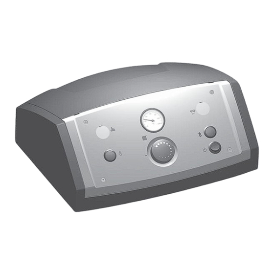
LAYOUT 1 - Overtemperature indicator 2 - Manual reset safety thermostat (110°C) 3 - Control thermostat (30-82°C) 4 - Boiler temperature gauge 5 - Fuse 6 - Burner lockout indicator 7 - Two pole ON/OFF switch 8 - Minimum temperature thermostat sensor (Tm) (accessible from inside) 9 - Safety thermostat sensor (TS) 10 - Control thermostat sensor (TR) 11- Boiler temperature gauge sensor (TeC) -
Page 16: Description Of Functions
DESCRIPTION OF FUNCTIONS RIELLOtech PRIME control panels are equipped with 3 homologated electromechanical thermostats, a temperature gauge, a main power ON/OFF switch, function indicators and a protective fuse. Main control panel ON/OFF switch ( b ) This switch connects power to all controlled devices and appliances. -
Page 17: Useful Information
USEFUL INFORMATION SELLER: INSTALLER: ............................................................Address Address ........................................................tel. tel............................................................. TECHNICAL ASSISTANCE SERVICE: ..............................Address ............................tel............................... BOILER DETAILS CONTROL PANEL DETAILS (From Data label): (From product label): Make Serial number ......................................................Type ............................................................ - Page 20 RIELLO S.p.A. - 37045 Legnago (VR) Tel. 0442630111 - Fax 044222378 - www.riello.it The manufacturer strives to continuously improve all products. Appearance, dimensions, technical specifications, standard equipment and accessories are therefore liable to modification without notice.
Need help?
Do you have a question about the RIELLOtech PRIME and is the answer not in the manual?
Questions and answers