Advertisement
Quick Links
HYDROLINE
COMANDO A BORDO PER IMPIANTI A 2
TUBI
1. Avvertenze preliminari
Questa
istruzione
è
dell'apparecchio sul quale viene installato il KIT. A tale
libretto si rimanda per le AVVERTENZE GENERALI e per le
REGOLE FONDAMENTALI DI SICUREZZA.
In alcune parti del libretto sono utilizzati i simboli:
ATTENZIONE= per azioni che richiedono particolare
cautela ed adeguata preparazione.
VIETATO= per azioni che non devono essere
assolutamente eseguite.
2. Versioni
Codici
20081467
Comando Plus a bordo 2T
3. Composizione del kit
1 Comando
2 Viti + tasselli ad espansione
3 Istruzioni di installazione
4 Cavo collegamento (cablato)
5 Staffa fissaggio comando
6 Sensore aria
7 Viti
8 Mastice
1
IT
parte
integrante
del
2
3
BUILT IN CONTROL FOR 2 PIPES SYSTEM
1. Preliminary instructions
libretto
This instruction booklet is an integral part of the manual
of the device on which you install the kit. In that manual,
please refer to the WARNINGS and the BASIC SAFETY RULES.
The following symbols are used in this publication:
WARNING = actions requiring special care and
appropriate training.
DO NOT = actions that MUST ON NO ACCOUNT be
carried out.
2. Versions
Codes
20081467
2T Built-in Plus control panel
3. Kit composition
1
1 Control
2
2 Screws + Screw anchors
1
3 Installation instruction
1
4 Connecting cable (wired)
1
5 Metal plate to fix the control
1
6 Air sensor
2
7 Screws
-
8 Sealing material
4
EN
5
7
Cod. 20081969 Rev. 1
1
2
1
1
1
1
2
-
6
8
Advertisement

Related Manuals for Riello HYDROLINE 20081467


Summary of Contents for Riello HYDROLINE 20081467
- Page 1 HYDROLINE COMANDO A BORDO PER IMPIANTI A 2 BUILT IN CONTROL FOR 2 PIPES SYSTEM TUBI 1. Avvertenze preliminari 1. Preliminary instructions Questa istruzione è parte integrante libretto This instruction booklet is an integral part of the manual dell’apparecchio sul quale viene installato il KIT. A tale of the device on which you install the kit.
- Page 2 HYDROLINE 4. Comando a bordo macchina 4. Unit-mounted control Aprire il comando rimuovendo la vite di sicurezza posta Open the control by removing the side security screw. lateralmente. Effettuare il collegamento del cavo in Connect the cable supplied as shown in the attached dotazione come da figura allegata (3a) in funzione del figure (3a) according to the type of control chosen.
- Page 3 HYDROLINE Cod. 20081969 Rev. 1...
- Page 4 HYDROLINE W.C C.HEAT C.COOL HF MF LF VALE 1 2 3 P5P4P3P2P1 Fig. ig. 2 A TO ELECTRONIC CONTROL - AL COMANDO ELETTRONICO VALE LF MF HF COOL HEAT Fig. 3 ig. 4 A Cod. 20081969 Rev. 1...
-
Page 5: Fan Operation
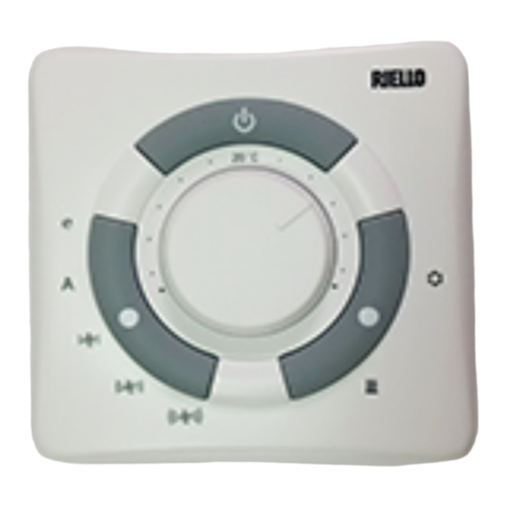
HYDROLINE 5. Funzioni 5. Functions Il comando viene utilizzato negli impianti a 2 tubi. Control is used in 2-pipe systems. Il comando provvede a mantenere la temperatura Control have a knob to select the temperature, with interna impostata dalla manopola tra 10°C e 30°C. a range from 10°C to 30°C, and room temperature is maintained at the selected value. -
Page 6: Frost Protection
HYDROLINE 7. Antigelo 7. Frost - protection La funzione antigelo permette di evitare in ambienti non This function keeps the temperature from dropping below frequentati per lunghi periodi che la temperatura scenda 7°C in rooms not used for long periods of time. sotto 7°C. -
Page 7: Button Operation
HYDROLINE selezione della velocità. The switching from one configuration to the other is Il cambio di configurazione è accompagnato da un segnale signalled by a light. The Green LED flashes 3 times when luminoso, 3 lampeggi del LED verde per il passaggio da switching from OFF to Energy Saving and the same green configurazione OFF a Energy Saving e LED verde acceso per LED remains ON for 3 seconds when switching from Energy... - Page 8 HYDROLINE 14. Indicazioni luminose 14. Light indicators LED blu Blue LED Acceso Indica che il comando è in modalità Indicates that the control is in cooling mode ( ). raffrescamento ( ). Flashing Indicates that the control is in frost protection Lampeggiante Indica che il comando è...
-
Page 9: Incorrect Configuration
HYDROLINE 16. Configurazioni “ponticelli” (microinterruttori) 16. “Dip-switch” configuration (microswitches) Ponticello 1 (P1) Dip-switch 1 (P1) Chiuso Antigelo ( ) disabilitato. Closed Frost protection ( ) disabled. Aperto Antigelo ( ) abilitato. Open Frost protection ( ) enabled. Ponticello 2 (P2) Dip-switch 2 (P2) Chiuso Ventilazione controllata dal termostato. - Page 10 HYDROLINE 20. Autotest 20. Autotest La funzione “Autotest” viene attivata tenendo premuto The “Autotest” function is activated by holding the il pulsante cambio stagionale e contemporaneamente seasonal changeover button pressed and at the same time premendo per tre volte il tasto di selezione delle velocità pressing the speed selection button three times within 1 entro 1 secondo.
- Page 11 HYDROLINE Cod. 20081969 Rev. 1...
- Page 12 HYDROLINE RIELLO S.p.A. - 37045 Legnago (VR) tel. +39 0442 630111 - fax +39 0442 22378 www.riello.it Poiché l’Azienda è costantemente impegnata nel continuo perfezionamento di tutta la sua produzione, le caratteristiche estetiche e dimensionali, i dati tecnici, gli equipaggiamenti e gli accessori, possono essere soggetti a variazione.
Need help?
Do you have a question about the HYDROLINE 20081467 and is the answer not in the manual?
Questions and answers