
Related Manuals for Trane MWC518


Summary of Contents for Trane MWC518
- Page 1 Indoor Unit Installation & Operation Manual Advanced Multi-split System Cassette Indoor Unit MWC518/524 R410A 200061360200 AMS-SVX02A-EN April 2012...
-
Page 2: Table Of Contents
Table of Contents User Notice Attention Unit Model Unit Components and Names Unit Installation Site Selection and Attentions Unit Installation Installation Diagram Panel Installation Electrical Control Wiring Electrical Wiring Electrical Parameters Electrical Wiring Diagram DIP Setting Wired Controller Instruction Fault Analysis Maintenance AMS-SVX02A-EN... -
Page 3: User Notice
User Notice Please review this manual carefully before installation It is our pleasure that you select air conditioning unit from Trane. Please review this manual carefully before installation and keep it safe for proper operation. User notice • During operation, the total capacity of the indoor units operating at the same time shall not exceed the outdoor unit capacity. -
Page 4: Attention
Attention Please read the information within this manual and carry out the operation in accordance with instructions. Please pay close attention to the following symbols: Warning A symbol indicating improper operation may cause personnel death or severe injury. Attention A symbol indicating improper operation may cause personnel injury or property damage. - Page 5 Attention Attention • Please verify the power supply meets requirements in the nameplate and check safety before installation. • Before operation, please check wires, drainage pipes and pipes connection avoiding accidents, such as water and refrigerant leakage, electric shock and fi re etc. •...
-
Page 6: Unit Model
Unit Model Model (Cassette indoor unit) Model Additional option Service code Digit 1 M = Trane mini split unit Digit 2 W = Heat pump C = Cooling only Digit 3 C = Cassette unit Digit 4 5 = Threaded connection... -
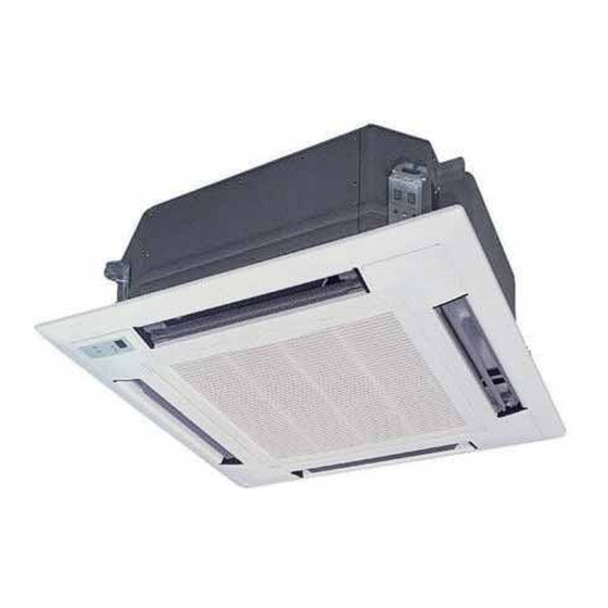
Page 7: Unit Components And Names
Unit Components and Names Drainage device (built-in type) Discharge condensate water from the indoor unit in cooling mode Drainage pipe Air defl ector (In the air outlet) Air outlet Connecting pipe Air strainer and purifi er (In the air inlet grille) Air inlet grille Figure 1. -
Page 8: Unit Installation Site Selection And Attentions
Attention Following locations may cause the air conditioning unit fault. If you have to select this kind of environment, please contact Trane service centre for help. Full of engine oil; Seaside saline area; Sulphuric gas (sulphuric hot spring);... - Page 9 Unit Installation Site Selection and Attentions Earthing • Air conditioning unit is Class I electric appliance and should be earthed reliably. • Yellow-green color line is earth line only for earthing and can not be broken. Self-tapping screw is not used for fi x, or it may cause electric shock. •...
-
Page 10: Unit Installation
Unit Installation Installation Diagram Over 20mm Air outlet Air outlet Air outlet Over 1,500mm Over 1,500mm Ground Figure 2. Verify indoor unit installation site Ensure no barriers in indoor unit air inlet and outlet for good ventilation. Ensure installation complying with the diagram. Select a low running noise and less vibration location which can support 4 times of indoor unit weight Ensure horizontal installation location. - Page 11 Only air conditioning unit installed by professionals in accordance with this manual can provide good function. • Please contact local Trane authorized service center before installation. When the unit installed by non-authorized service center is failure, we can not resolve it in time for business relations.
- Page 12 Unit Installation • Only professional can drill holes in the ceiling Main stand Ceiling Over 20 Description: Dimension of ceiling hatches with * can be 910mm, but the overlapping section between the ceiling and decoration panel should be over 20mm. Hoisting Main Unit of Air Conditioning Preliminarily install the indoor unit.
- Page 13 Unit Installation Nut (provided on-site) Washer (accessory) Insert Hanger bracket Washer guide plate (accessory) Tighten (double nut) [Fix the hanger bracket] [Fix the washer] Fix the screw at the corner of outlet pipe at the drainage tank corner Center of the Installation paperboard ceiling hatch Level...
-
Page 14: Panel Installation
Unit Installation Panel Installation As shown in Fig.6, place the air defl ector motor facing indoor unit pipe mouth. Panel installation Install the panel on the indoor unit temporarily. Put the buckle at the hook (2 positions) in the opposite air defl ector motor side. Put the residual 2 buckles at the main hook temporarily (air defl... - Page 15 Unit Installation Attentions Improper screw tightness may cause fault as shown in fi g. 7. Air leakage Ceiling air leakage Water drop condensed and fall Figure 7. If there is still a seam between ceiling and decoration panel after tightening screws, please adjust the indoor unit height again (as shown in fi...
- Page 16 Unit Installation Refrigerant pipe connection • As shown in fig. 10, use wrench and torque wrench simultaneously for removing or installing pipes. • Apply refrigerating engine oil on the tapered nut inside and outside, and then tighten it after 3-4 turns manually. •...
- Page 17 Unit Installation Drainage pipe Installation • Diameter of the drainage pipe should be larger than or equal to the connecting pipe diameter (PE pipe outer diameter is 25mm and wall thickness is larger than or equal to 1.5mm). • Drainage pipe should be as short as possible and the gradient shall be 1/100 at least to prevent air pocket formation.
- Page 18 Unit Installation Roof Hanger bracket Less than 300mm 1-1.5m Less than 280mm Drainage hose (accessory) Drainage lift pipe 220mm Ceiling Clamp (accessory) Figure 13. Explanation • The inclination of supplied drainage hose shall not exceed 75mm, allowing the drainage socket not have to bear additional external force. •...
-
Page 19: Electrical Control Wiring
Electrical Control Wiring Electrical Wiring Attention All indoor units must be powered by the same power supply system. • See attached Wiring diagram for electrical working. • Only professionals can carry out all installations. • Please take earthing measures. Unit Connecting and Communication Cable •... - Page 20 Electrical Control Wiring Power and Communication Wiring of Wired Controller Main board CN17 Special 2-core shielded wire Bottom of wire controller display board Figure 17. Power and communication wiring of wired controller It is power and communication wiring diagram of wired controller above. Insert 2-core shielded wire from main board CN17 into terminal CN1 of display board.
-
Page 21: Electrical Parameters
Electrical Control Wiring The first indoor unit The second indoor unit The third indoor unit To the outdoor unit Connection of Power Wire Attention All indoor units are powered in the same way. Air conditioning unit using single phase power Remove the electrical appliance box cover. -
Page 22: Electrical Wiring Diagram
Electrical Wiring Diagram Cassette indoor unit 2 Blue Swing motor Limit switch Limit switch Power supply 1 Brown Black Black 3 Yellow/green 20Red 19White 21Black 22Black CN21 CN20 CN10 CN11 Communication wire Ambient CN15 CN19 FUSE:50T 3.15A 250V~ temperature sensing bulb Communication wire CN16 Outlet... -
Page 23: Dip Setting
DIP Setting Cassette indoor unit PCB board DIP setting Indoor fan gear With/without RAM Indoor unit capacity DIP Reserved selection setting Indoor unit address DIP Reserved Reserved Test program Indoor unit capacity DIP According to the capacity, the indoor unit is divided into various models, such as 5.0 kW and 7.1kW etc. -
Page 24: Wired Controller Instruction
Wired Controller Instruction Buttons TEMP. setting/ Time setting Quick cooling Quick heating/ Timing function PRI setting / Time Inquiry, set Fan speed setting Swing function button Sleep setting MODE MODE Mode selection ON/OFF TM-07 The diagram is just for reference, the actual display may be different. When you press a button, there may be no action since non corresponding function. - Page 25 Wired Controller Instruction ON/OFF Button Sleep function Display Press ON/OFF button to turn on the unit, and repress this While operating in sleep mode, this animation displays button to turn off the unit. At the time of startup, the unit runs 12 Display of operating in auto mode in the present setting.
-
Page 26: Fault Analysis
Fault Analysis If your air conditioning function is improperly, please check followings before call for service: Fault Possible causes 1. Do not connect power supply. The air conditioning can not startup 2. Leakage switch trips caused by leakage 3. Low voltage The air conditioning will stop after a 1. -
Page 27: Maintenance
Maintenance Attention Please pay attention to followings before cleaning • Before contact the wiring device, make sure indoor unit main power supply has been cut off. • Only clean the unit after shutoff and cut off main power supply otherwise may cause electric shock or injury. - Page 28 April. 2012 Trane Supersedes www.trane.com For more information, contact your local Trane Trane has a policy of continuous product and product data improvement and reserves the right to office or e-mail us at comfort@trane.com change design and specifi cations without notice.
Need help?
Do you have a question about the MWC518 and is the answer not in the manual?
Questions and answers