
Related Manuals for Trane MWD507


Summary of Contents for Trane MWD507
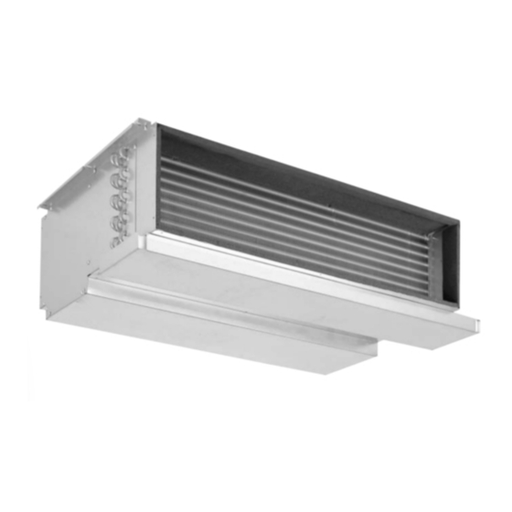
- Page 1 Indoor Unit Installation & Operation Manual Advanced Multi-split System Concealed Indoor Unit MW(C)D507-524 R410A 200061230200 AMS-SVX04A-EN April. 2012...
-
Page 2: Overview
For more detailed information or special problem proposed by customers but not detailed in this manual, please contact TRANE. AMS-SVX04A-EN... -
Page 3: Table Of Contents
Table of contents Overview Safety instruction Model descriptions Unit dimension Standard model Slim model Unit installation Precautions Installation of the concealed indoor unit Installation of refrigerant pipe Three principles of installing the refrigerant pipe Flared coupling of the refrigerant pipe Welding of refrigerant pipe Purging of refrigerant pipe Leakage detection and heat insulation of refrigerant pipe... -
Page 4: Safety Instruction
Safety instruction Caution Please read this installation manual carefully and be sure to comply with the instructions in this manual before installing and using this unit! For this product, the following standards apply: GB/T 18837-2002 JB 8655-1997 GB 4706.1-2005 Preparation before installation •... - Page 5 Safety instruction Precautions during trial operation • Do not operate the wired controller or remote controller with wet hands. Do not splash water into the wired controller or remote controller. • Do not pull or bend the cable of the wired controller. Never use sharp object press the button, and avoid improper connection.
-
Page 6: Model Descriptions
Electric heater N = Without electric heater(cooling only model can only choose this option) C = With 1.0 kW electric heater (only for MWD507 , 509, 510) D = With 1.4 kW electric heater (only for MWD511, 512) F = With 1.8 kW electric heater (only for MWD516, 518) H = With 2.8 kW electric heater (only for MWD524) -
Page 7: Unit Dimension
Unit dimension Standard model 1. Only main unit, no accessories selected by the customer: MW(C)D509~524MM*** Centrifugal fan Hoisting hole (4), see detail A Motor Inlet Outlet Unit weight pipe Ø pipe Ø (Kg) Model MW(C)D509MM 1/4" 3/8" 18.5 MW(C)D512MM 1/4" 1/2"... -
Page 8: Slim Model
Unit Dimension Slim model 1. Only main unit, no accessories selected by the customer: MW(C)D507~518NM*** Centrifugal fan Motor Hoisting hole (4), see detail A Unit weight Inlet Outlet pipe Ø pipe Ø (Kg) Model MW(C)D507/509/510 1/4" 3/8" MW(C)D511/512 1/4" 1/2" MW(C)D516/518 1153 3/8"... -
Page 9: Unit Installation
Unit installation Precautions • Be sure to take out the indoor unit from the packing case. When handling the air conditioner, please hold the stress area of the air conditioner, such as lifting lug etc., not the steam pipe, liquid pipe or drainage pipe; •... - Page 10 Unit Installation Installation of the indoor unit with ducts refers to the following fi gure. Mounting roof Ceiling Return air Supply air A enlarged Wide expansion bolt Hanging screw Unit Wide lock washer Supply air channel Roof plate with screws B rivet Unit roof plate Supply air channel...
- Page 11 Unit Installation Support the unit fi rmly. Remove the junction box lid to connect the wire with the terminals. Make sure that there are enough space for maintenance, as shown in the fi gure (A Unit length Width); Select a place for hanging. Mount the suspension rod, and fi x it fi rmly; Check whether the suspension rod is aligned with the unit, and lift the unit on the suspension rod;...
- Page 12 Unit Installation Preparation and installation of air duct Precautions • When designing the air duct, please design the air channel according to the external static pressure of the unit. The resistance of the air channel is equal to the static pressure; otherwise, the air volume may be too large or small, resulting in failure of unit operation;...
- Page 13 Unit Installation Installation of air outlet duct • The air outlet duct may be rectangle or round: rectangle duct may be connected directly to the air outlet of the indoor unit with rivets; round duct should be connected to the air outlet of the indoor unit after adding a transition duct, and another end may be separate or be connected to the air outlet grille, as shown in following fi...
-
Page 14: Installation Of Refrigerant Pipe
Installation of refrigerant pipe Three principles of installing the refrigerant pipe Cause Measures against failure Rainwater, water for engineering invaded from outside Drying Processing Purging Vacuum drying Invasion of condensate water in the pipe Oxide formed in the pipe during welding Replace nitrogen gas Cleaning Dust, impurities invaded from outside... -
Page 15: Welding Of Refrigerant Pipe
Installation of refrigerant pipe Welding of refrigerant pipe • Make downward or fl at lateral welding, and avoid overhead welding as possible; • For liquid or gas pipes, be sure to care the assembling direction and angle, and avoid refrigerant short circuit or oil accumulation;... -
Page 16: Leakage Detection And Heat Insulation Of Refrigerant Pipe
Installation of refrigerant pipe • Purging: Sustain the liquid pipe of the indoor unit with the insulating material in the hand. When it is incapable to resist due to change of pressure, remove the insulating material quickly, and make the nitrogen blow off fast from the pipe mouth (fi rst purging). Then resist the pipe mouth with the insulating material (second purging). -
Page 17: Precautions
Installation of refrigerant pipe Precautions • Before connecting the drainage pipe, fi rst dismount the drain plug on the left or right side of the bottom plate; • The condensate pipe should be as short as possible drains in run-off elevation (under way), avoid the drainage pipe up and down, and prevent counter fl... -
Page 18: Concentrated Drainage
Installation of refrigerant pipe Concentrated drainage Please select the drainage pipe with a diameter adapting to the running capacity of the unit. Without drainage pump: (Slim line) Duct type Indoor unit Indoor unit Indoor unit ≥100 Concentrated drainage pipe, gradient ≥ 1/100 Ceiling With drainage pump: When 3 or more indoor units are installed, a main air vent is provided for the indoor unit having a... -
Page 19: Electrical Control Wiring
. If electric heater is provided for the unit, the specifi cation for power line should be improved accordingly; It is suggested that conductors provided by Trane factory is used for the communication lines of the indoor and outdoor units. The shield twisted pair is 0.5 ~ 1.25 mm , twist pitch is less than 10 Control signal has A and B polarities. -
Page 20: Dip Setting Of The Controller
Electrical control wiring Plug the terminal of shielded communication line in corresponding place of the wired controller. To wired controller Cover the front cover plate of the wired controller. DIP setting of the controller DIP for model of indoor unit DIP for address of indoor unit Shift selection of indoor fan DIP for model of the indoor unit If model of the indoor unit differs, the DIP setting of the control panel is different. -
Page 21: Dip For Address Of The Indoor Unit
Electrical control wiring DIP for address of the indoor unit Different indoor units are identifi ed according to different DIP switches for address of the indoor unit. The address DIP must be different (in case of being identical, a failure of address confl ict will be incurred). -
Page 22: Electrical Parameters
Electrical control wiring Electrical parameters Standard model Without electric heatier With electric heater Frequency Rated Range of Rated current Rated current voltage voltage of fan motor Min. Min. of electric Min. line Min. line specification specification heater Model current current for diameter for diameter (optional) -
Page 23: Description Of Controller
Description of controller Operating panel of wired controller Buttons TEMP. setting/ Time setting Quick cooling Quick heating/ Timing function PRI setting / Time Inquiry, set Fan speed setting Auxiliary heating function button Sleep setting MODE MODE Mode selection ON/OFF TM-07 Warning: In winter, if the ambient temperature is below 16 ºC, please do not switch off the power, and preheat the unit 24 hours ahead before startup, or the compressor may be damaged. - Page 24 Description of controller Instruction to operation of the wired controller ON/OFF Press button Sleep function Display While operating in sleep mode, this animation Press ON/OFF button to turn on the unit, and repress this button to turn displays off the unit. At the time of startup, the unit runs in the present setting. Display of operating in auto mode Temperature (time) setting buttons Display of operating in fan mode...
-
Page 25: System Parameter Query List
Description of controller System parameter query list Press the Sleep button for 5s, the buzzer gives a sound, enter the query mode, the query address is displayed in the temperature display area, the clock indicates the parameter, press ▲ or ▼ once, and the query address is switched once. -
Page 26: Electrical Wiring Diagram
Electrical wiring diagram MW(C)D507 ~ 518, without condensate water lift pump AMS-SVX04A-EN... - Page 27 Electrical wiring diagram MW(C)D524, without condensate water lift pump AMS-SVX04A-EN...
- Page 28 Electrical wiring diagram MW(C)D507 ~ 518, with condensate water lift pump AMS-SVX04A-EN...
- Page 29 Electrical wiring diagram MW(C)D524 with condensate water lift pump AMS-SVX04A-EN...
- Page 30 Literature Order Number AMS-SVX04A-EN Date April. 2012 Trane Supersedes www.trane.com For more information, contact your local district Trane has a policy of continuous product and product data improvement and reserves the right to offi ce change design and specifications without notice.
Need help?
Do you have a question about the MWD507 and is the answer not in the manual?
Questions and answers