Trane MCC Series Installation Manual
Cassette split system, 1-5 tons 18,000 - 38,000 btu underceiling type
Hide thumbs
Also See for MCC Series:
- Owner's manual (30 pages) ,
- Installation operation & maintenance (32 pages) ,
- Installation manual (28 pages)

Related Manuals for Trane MCC Series


Summary of Contents for Trane MCC Series
- Page 1 Installation Manual CASSETTE Split System, 1-5 Tons 18,000 - 38,000 Btu Underceiling Type MCC Series 50 Hz Models Cooling Only MCC 518 AB MCC 524 AB MCC 530 AB MCC 536 AB February 2000 MCC-SVN01A-EN...
-
Page 2: General Information
Trane MCC series offer ceiling For installing the unit to operate mounted installation to leave the floor Your personal safety and the proper... -
Page 3: Table Of Contents
Contents General Information Indoor Unit Installation Outdoor Unit Installation Connection of Refrigerant Tubing and Condensate Drain Piping Leak Check and System Evacuation Electrical Installation Wiring Diagram Dimensional Data Notes MCC-SVN01A-EN... -
Page 4: Indoor Unit Installation
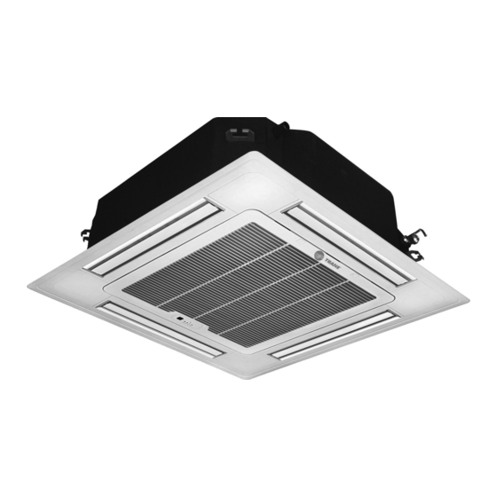
Indoor Unit Installation • Hang the four mounting rods to the • Install the leveling metal plate to Where to install Indoor Unit positions marked as picture shown adjust the gap between the unit • There should not be any heat in figure 3 (using twelve nuts and and a ceiling, fixing the screws source or steam near the unit. -
Page 5: Outdoor Unit Installation
Outdoor Unit Installation Where to install Outdoor more than 10 cm. more than 10 cm. Unit • The foundation must be solid enough to bear the weight and more than 10 cm. vibration of the unit. • The space around the unit is more than 35 cm. -
Page 6: Connection Of Refrigerant Tubing And Condensate Drain Piping
Connection of Refrigerant Tubing and Condensate Drain Piping 10. Tighten the flare nut to the Connecting the unit with flaring A good flare should have the specified tightening torque with procedure following characteristics: torque wrench and adjustable 1. Flaring (If piping is procured or cut Inside surface is glossy and wrench. -
Page 7: Leak Check And System Evacuation
Leak Check and System Evacuation 8. Close valve on the R-22 supply Leak Check Procedure cylinder. Close valves on manifold After the connection operation of 1. Connect R-22 drum with gauge gauge set and remove refrigerant refrigerant lines to both the outdoor manifold to the Schrader valves charging hoses from liquid and and indoor unit is completed, the field... -
Page 8: Electrical Installation
Electrical Installation All wiring and grounding must comply Indoor Unit with local electrical codes. Remove the right side panel and 1. Wiring return grille (see previous instructions), Important Safeguards: to access the terminal base. - Check the unit nameplate for Pass the system wiring through electrical rating. -
Page 9: Wiring Diagram
Wiring Diagram 220-240/1/50 Hz MCC518-536AB MCC-SVN01A-EN... -
Page 10: Dimensional Data
Dimensional Data Model MCC518AB MCC524AB MCC530AB MCC536AB A. Height above ceiling 290 mm. 290 mm. 340 mm. 340 mm. B. Height above suspension brackets 180 mm. 180 mm. 230 mm. 230 mm. C. Height of condensate drain above ceiling 230 mm. 230 mm. 280 mm. 280 mm. D. -
Page 11: Notes
Notes MCC-SVN01A-EN... - Page 12 Stocking Location Bangkok, Thailand 2 Sukhumvit Road, Klongtoey Bangkok 10110 http://www.trane.com Since The Trane Company has a policy of continuous product and product data improvement, An American Standard Company it reserves the right to change design and specifications without notice.
Need help?
Do you have a question about the MCC Series and is the answer not in the manual?
Questions and answers