Table of Contents
Advertisement
ALL phases of this installation must comply with NATIONAL, STATE AND LOCAL CODES.
IMPORTANT — This Document is customer property and is to remain with this unit. Please return to service informa-
tion pack upon completion of work.
These instructions do not cover all variations in systems or provide for every possible contingency to be met in
connection with the installation. Should further information be desired or should particular problems arise which are
not covered sufficiently for the purchaser's purposes, the matter should be referred to your installing dealer or local
distributor.
Single Split
Indoor Unit
Heat Pump
M4MHW17-A
Cooling Only
M4MCW17-A
Installer's Guide
17 Series System (R-410A)
Mini-Split, Inverter System
Single Zone
Outdoor Unit
M4THS17-A
M4TCS17-A
88-M4MHW17-1A-EN
Advertisement
Table of Contents

Related Manuals for Trane RunTru 17 Series


Summary of Contents for Trane RunTru 17 Series
- Page 1 88-M4MHW17-1A-EN Installer’s Guide 17 Series System (R-410A) Mini-Split, Inverter System Single Zone ALL phases of this installation must comply with NATIONAL, STATE AND LOCAL CODES. IMPORTANT — This Document is customer property and is to remain with this unit. Please return to service informa- tion pack upon completion of work.
- Page 2 Installer's Guide Warnings and Cautions Warnings are provided to alert others of the potential hazards that could result in severe personal injury or death, while cautions are designed to alert others of the conditions that could result in minor or moderate injury. Your personal safety and the proper operation of this machine depend upon the strict observance of these precautions.
- Page 3 Installer's Guide Warnings and Cautions WARNING R410-A Refrigerant under Higher Pressure than R-22! The units described in this manual use R410-A refrigerant which operates at 50 to 70% higher pressures than R-22. Use only R-410A approved service equipment. Refrigerant cylinders are painted with "pink" color to indicate the type of refrigerant and may contain a "dip"...
-
Page 4: Table Of Contents
Installer's Guide Table of Contents Safety Precautions ........................5 Pre-Installation Checklist ......................6 Items Shipped With the System ....................7 Necessary Tools ........................7 Typical Installation Setup ......................8 Names and Functions of Each Part ................... 8 Clearance Requirements ......................9 Connection Pipe Requirements .................... -
Page 5: Safety Precautions
Installer's Guide Safety Precautions Your personal safety and the proper operation of this equipment depend upon the strict observance of these precautions. This mark indicates a potentially hazardous situation which, if not avoided, WARNING could result in death or serious injury. This mark indicates a potentially hazardous situation which, if not avoided, CAUTION could result in minor or moderate injury. -
Page 6: Pre-Installation Checklist
Installer's Guide 12. If a system pump-down is performed, turn off the associated equipment and close service valves prior to removing the refrigerant piping. Failure to do so will introduce non-condensables in the system, causing abnormal pressure in the refrigeration cycle which could lead to injury and damage. 13. -
Page 7: Items Shipped With The System
Installer's Guide Items Shipped with the 17 Series Mini-Split System After unpacking the unit(s), please refrain from disposing of the packaging materials until items listed below are located. If any of these are missing, please contact the point of sale to obtain these items. Indoor Unit 1. -
Page 8: Typical Installation Setup
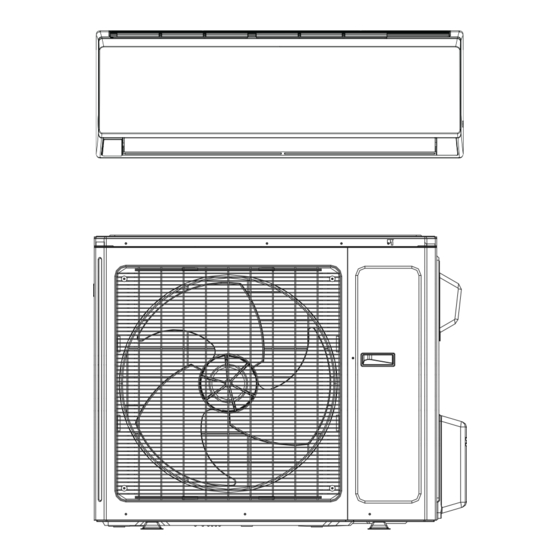
Installer's Guide Typical Installation Setup Indoor Unit 1 - Front Panel 2 - Filter 3 - Guide Louver (10) 4 - Wall Pipe* 5 - Bind Tape* 6 - Connection Wire* (Sold Separately) 7 - Drainage Pipe* 8 - Power Cable* 9 - Wired Controller Outdoor Unit (Sold Separately) -
Page 9: Clearance Requirements
Installer's Guide Clearance Requirements Space to the ceiling 6 in. or more Space to the wall 6 in. or more 6 in. or more Space to the wall 118 in. or more or more Air outlet side Space to the floor The dimensions of the space necessary for correct installation of the appliance including the minimum permissible distances to adjacent structures... -
Page 10: Connection Pipe Requirements
Installer's Guide Connection Pipe Requirements NOTICE The maximum length of the connection pipe is listed in the table below. Do not place the units such that the distance between them exceeds the maximum length of the connection pipe. M4THS1709A M4THS1712A M4THS1718A M4THS1724A Heat Pump... -
Page 11: Refrigerant Piping Precautions
Installer's Guide Refrigerant Piping Precautions WARNING Hazard of Explosion and Deadly Gases! Failure to follow all proper safe refrigerant handling practices could result in death or serious injury. Never solder, braze or weld on refrigerant pipes or any unit components that are above atmospheric pressure or where refrigerant may be present. -
Page 12: Installation Location
Installer's Guide Installation Location Indoor Unit WARNING Adequate Support Required! The wall structure must be adequate to support the weight of the unit. Failure to ensure adequate structural support could result in death, serious injury, and equipment or property damage. 1. -
Page 13: Installing The Indoor Unit
Installer's Guide Installing the Indoor Unit WARNING Hazardous Service Procedures! The maintenance and troubleshooting procedures recommended in this section of the manual could result in exposure to electrical, mechanical or other potential safety hazards. Always refer to the safety warnings provided throughout this manual concerning these procedures. -
Page 14: Drilling The Piping Hole
Installer's Guide 09K: 12K: Wall Wall Wall Wall Mark in the middle of it Level Level Mark in the middle of it Space Space Space Space to the to the to the to the wall wall wall wall min. min. min. -
Page 15: Refrigerant Piping At The Indoor Unit
Installer's Guide NOTICE If a wall sleeve is not used, unnecessary damage to the piping and wiring could occur. This typically results in current loss, improper grounding, and pipe leaks, Ensure no undue forces are on the piping and wiring through wall(s) and adequate draining still occurs. Refrigerant Piping at the Indoor Unit Note: Until the outdoor unit is set and ready to connect refrigeration pipes, do not remove the caps from the indoor unit. - Page 16 Installer's Guide 6. After evacuation is complete, additional charge can be added. a) If no additional charge is required, break the vacuum with refrigerant, then remove the gauge connectors. b) slightly open the liquid valve at the OD unit, allow system to equalize, then fully open the liquid valve and then open the vapor service valve.
-
Page 17: Installing The Condensate Pipe
Installer's Guide Installing the Condensate Pipe NOTICE Do not sharply twist or curve the condensate drain pipe. Ensure pipe ends are not submerged in water. Drain pipe must provide adequate flow and slope downward to the outlet. Failure to do so may result in leakage and overflow of the drain pan. - Page 18 Installer's Guide 3. Remove the wire clip and connect the power connection wire to the wiring terminal according to the correct color coding. It is recommended to use 4 wire colors (for example: Blue, Black, Red, Green. Connect Blue to 1, Black to 2, Red to 3 and Green to Ground). All wiring shall use ring or spade type crimped or soldered connectors (as shown in the outdoor unit installation section or manual).
-
Page 19: Binding The Pipes And Cables
Installer's Guide Binding the Pipes and Cables Note: The refrigeration pipes shall be insulated separately to prevent heat transfer between the two pipes. 1. At the beginning of the indoor connections, bind the insulated refrigerant pipes, power cable, and drain hose by evenly wrapping them with an appropriate pipe tape. 2. -
Page 20: Installing The Outdoor Unit
Installer's Guide Installing the Outdoor Unit WARNING 1. Install the unit on a level surface or on supports that are level. 2. If the location is subject to strong winds, the additional force must be accounted for and the unit must be fixed securely to the base. Refer to local codes for additional requirements. When the outdoor unit is surrounded by walls or other obstructions, the installation space of the unit should be no less than the clearances indicated below. -
Page 21: Installing The Refrigerant Piping
Installer's Guide 4. Place the outdoor unit on the support base. 5. Secure the foot holes of the outdoor unit with bolts (shown below). Foot holes Foot holes Installing the Refrigerant Piping Flaring Process 1. Hold the pipe downward to prevent cuttings from entering the pipe. 2. -
Page 22: Refrigerant Piping At The Outdoor Unit
Installer's Guide 4. Do not bend the pipe while insulated. First, cut the insulation with a sharp cutting tool and expose it to the appropriate bend radius, as shown below. After bending the pipe, replace the insulation and seal it with pipe wrap tape. NOTICE 1. -
Page 23: Piping Requirements
Installer's Guide Piping Requirements If the outdoor unit is installed lower than the indoor unit: 1. A drain pipe should be above ground and the end of the pipe should not dip into water. 2. Taping pipes must be done from bottom to top. Do not wrap too tightly to avoid compression of the insulation, otherwise its effectiveness is reduced. -
Page 24: Vacuum And Refrigerant Leakage Detection
Installer's Guide Vacuum and Refrigerant Leakage Detection NOTICE Do not purge the air with refrigerant. Use a vacuum pump to vacuum the installation! 1. When connecting refrigerant pipe to the unit or removing it from the unit, please use both a back-up wrench and the torque wrench. -
Page 25: Wiring Precautions
Installer's Guide Wiring Precautions WARNING 1. Before obtaining access to terminals, all supply circuits must be disconnected. 2. Improperly installed and grounded field wiring poses fire and electrocution hazards. For high voltage connections, flexible electrical conduit is recommended whenever vibration transmission may create a noise problem within the structure. -
Page 26: Stranded Wiring Connections
Installer's Guide Stranded Wiring Connections Cut the wire end with a wire cutter or wire cutting pliers, then strip the insulation about 3/8" (10mm). 1. Using a screwdriver, remove the terminal screw(s) on the terminal board. 2. Using a round terminal fastener or pliers, securely clamp a round terminal to each stripped wire end. -
Page 27: Electrical Connections
Installer's Guide Electrical Connections CAUTION Improper operation may lead to personal injury or property damage. Size the power supply wiring according to the NEC, local code and the MCA indicated on the unit nameplate. Electrical Requirements Heat Pump Models M4THS1709 M4THS1712 M4THS1718 M4THS1724... -
Page 28: Power Supply Wiring
Installer's Guide Power Supply Wiring 1. Open the side covering plate. 2. Connect the power wiring to the terminals "L1", "L2" and also to the grounding bolt, and then connect the wiring terminals "N(1), 2, 3" of the indoor unit to those of the outdoor unit correspondingly. -
Page 29: Post Installation Checklist
Installer's Guide Post Installation Checklist Check the following points before testing the unit: Item to be checked Possible problem Have the indoor and outdoor units been The units may fall, vibrate or make noise. securely installed? Has the refrigerant leak test been Unresolved leaks may cause insufficient completed? cooling or heating. -
Page 30: Refrigerant System Diagrams
Installer's Guide Refrigerant System Diagram Cooling Only Models Indoor unit Outdoor unit Gas pipe side Valve Di s charge Heat exchanger (evaporator) Suction Accumlator Compressor Heat exchanger Liquid pipe (condenser) side Valve Capillary Strainer Heat Pump Models Outdoor unit Indoor unit Gas pipe side Valve... -
Page 31: Wiring Diagrams
Installer's Guide Wiring Diagrams Color Key Symbol Symbol Color Symbol Symbol Color Symbol Name White Green Jumper cap Yellow Brown COMP Compressor Blue Grounding wire YE/GN Yellow/Green Black Violet Orange Note: Jumper cap is used to determine fan speed and the swing angle of horizontal louver for this model. - Page 32 Installer's Guide Outdoor Cooling Only Unit 9K-12K N(1) NOTE: Motor ground only applies to metal clad motors. Outdoor Heat Pump Only Unit 9K-12K N(1) NOTE: Motor ground only applies to metal clad motors. These diagrams are subject to change without notice, please refer to the diagram supplied with the unit. NOTE: The wiring diagrams in this guide are included as a reference.
- Page 33 Installer's Guide Outdoor Cooling Only Unit 18K-24K N(1) Outdoor Heat Pump Only Unit 18K-24K N(1) These diagrams are subject to change without notice, please refer to the diagram supplied with the unit. NOTE: The wiring diagrams in this guide are included as a reference. The manufacturer has a policy of continuous product and product data improvement and reserves the right to change design and specifications without notice.
-
Page 34: Unit Dimensions
Installer's Guide Indoor Unit Dimensions 9K-12K Indoor Units 6 5/8 18 3/16 6 5/16 Φ2 3/16 Φ2 3/16 2 1/8 2 1/8 3 1/2 4 11/16 21 5/16 7 1/4 Φ2 3/16 Φ2 3/16 1 3/8 1 3/8 3 5/16 Unit:inch The dimensions in these drawings MODEL... - Page 35 Installer's Guide Indoor Unit Dimensions, continued 18K-24K Indoor Units 3/16 Φ2 3/16 Φ2 3/16 1 1/2 1 1/2 7 1/2 5 1/2 8 1/8 7 5/16 Φ2 3/4 Φ2 3/4 1 11/16 1 11/16 3 1/8 Unit:inch Models The dimensions in these drawings 38 1/4 11 13/16 8 7/8...
- Page 36 Installer's Guide Outdoor Unit Dimensions 9K-12K Outdoor Units 10 1/8 12 5/8 30 5/8 The dimensions in these drawings are rounded according to standard measurement. 18K-24K Outdoor Units 13 3/8 15 1/4 Unit: inch 88-M4MHW17-1A-EN...
-
Page 37: Common Error Codes
Installer's Guide Common Error Codes Error Codes Malfunction Type Possible Causes 1. Jumper cap missing from the control board. 2. Incorrect or damaged jumpercap on System Configuration Malfunction control board. 3. Indoor and outdoor units are not compatible. 1. Overcharged with refrigerant. High Pressure 2. - Page 38 Installer's Guide Error Codes Malfunction Type Possible Causes 1. Improper or low voltage at the IPM module. IPM Module Protection 2. IPM module malfunction. 3. Compressor Malfunction. 1. Loose connections between fan motor and control board. Indoor DC Fan Motor Malfunction 2.
-
Page 39: Troubleshooting
Installer's Guide Troubleshooting WARNING Improper operation may lead to personal injury or casualty. • Turn off the main power switch immediately if a malfunction is detected. Contact the installing dealer or qualified service technician. If the unit continues to run during a malfunction, the unit may be damaged or electric shock or fire may occur. -
Page 40: Auxillary Operation
Installer's Guide Auxiliary Operation If the remote controller is lost or damaged, please use the auxiliary button to turn on or turn off the air conditioner. Open the front panel of the unit and press the aux. button to turn on or turn off the unit. -
Page 41: General Maintenance
Installer's Guide General Maintenance Regular checks, maintenance and care should be performed by professional personnel, which will prolong the unit life span. Outdoor Heat Exchanger The outdoor heat exchanger should be checked and cleaned once every two months. Use a vacuum cleaner with a nylon brush to clean up dust and debris on the surface of the heat exchanger. - Page 42 About Trane and American Standard Heating and Air Conditioning Trane and American Standard create comfortable, energy efficient indoor environments for residential applications. For more information, please visit www.trane.com or www.americanstandardair.com The AHRI Certified mark indicates company participation in the AHRI Certification program. For verification of individual certified products, go to ahridirectory.org.
Need help?
Do you have a question about the RunTru 17 Series and is the answer not in the manual?
Questions and answers