Panduit Atlona OmniStream 111 Installation Manual
Single-channel networked av encoder
Hide thumbs
Also See for Atlona OmniStream 111:
- User manual (105 pages) ,
- Installation manual (12 pages)
Table of Contents
Advertisement
Quick Links
OmniStream 111 Single-Channel Networked AV Encoder
AT-OMNI-111
The Atlona OmniStream™ 111 (AT-OMNI-111) is a single-channel networked AV encoder for
HDMI 2.0 sources up to 4K @ 60 Hz and HDR (High Dynamic Range), plus embedded audio
and RS-232 or IR control pass-through. It is part of the OmniStream Series, designed for high
performance, flexible distribution of AV over standard off-the-shelf Gigabit Ethernet switches in
commercial audio visual applications. The OmniStream 111 is HDCP 2.2 compliant and ideal
for the latest Ultra High-Definition and HDR sources. It features advanced high-quality VC-2
visually lossless video compression technology for computer-generated imaging, or motion video
content. The Atlona OmniStream™ 111 achieves extremely low, sub-frame latency when paired
with OmniStream Decoders. This single-channel encoder is housed in a half-width rack with
front-to-back air flow enclosure, and is ideal for high-density, compact installation in a centralized
equipment location.
Package Contents
1 x AT-OMNI-111
1 x Push spring connector, 6-pin
1 x Wall/table mounting brackets
4 x Rubber feet
1 x Installation Guide
IMPORTANT: Visit http://www.atlona.com/product/AT-OMNI-111 for the latest
firmware updates and User Manual.
1
Installation Guide
AT-OMNI-111
Advertisement
Table of Contents

Related Manuals for Panduit Atlona OmniStream 111


Summary of Contents for Panduit Atlona OmniStream 111
- Page 1 Installation Guide AT-OMNI-111 OmniStream 111 Single-Channel Networked AV Encoder AT-OMNI-111 The Atlona OmniStream™ 111 (AT-OMNI-111) is a single-channel networked AV encoder for HDMI 2.0 sources up to 4K @ 60 Hz and HDR (High Dynamic Range), plus embedded audio and RS-232 or IR control pass-through. It is part of the OmniStream Series, designed for high performance, flexible distribution of AV over standard off-the-shelf Gigabit Ethernet switches in commercial audio visual applications.
-
Page 2: Operating Notes
Installation Guide AT-OMNI-111 Operating Notes • Atlona recommends using the Atlona Management System (AMS) which provides discovery, management, and configuration assistance. AMS is a free application that can be downloaded from the Atlona web site at http://atlona.com/product/at-sw-ams/. • This product includes a built-in web interface, which can be used to manage and configure this device. -
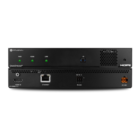
Page 3: Panel Descriptions
Installation Guide AT-OMNI-111 Panel Descriptions HDMI LINK TREAM RX TX DC 48V HDMI IN ETHERNET RS-232 AT-OMNI-111 HDMI IN This LED indicator glows bright green when Connect an HDMI cable from this port to an the unit is powered. HD source. HDMI ETHERNET This LED indicator shows the input status. -
Page 4: Mounting Instructions
Installation Guide AT-OMNI-111 Mounting Instructions The AT-OMNI-111 encoder includes two Repeat steps 1 through 4 to attach the mounting brackets and four mounting screws, second mounting bracket to the opposite which can be used to attach the unit to any flat side of the unit. -
Page 5: Installation
Installation Guide AT-OMNI-111 Installation Connect an Ethernet cable from the ETHERNET port on the encoder to a PoE-capable switch on the Local Area Network (LAN). Note that if a PoE-capable switch is not available, the 48V DC power supply (sold separately) must be connected to the encoder. Connect an HDMI cable from a UHD/HD source to the HDMI port on the encoder. - Page 6 Installation Guide AT-OMNI-111 RS-232 The AT-OMNI-111 provides transport of RS-232 protocol over IP which allows communication between a control system and an RS-232 device. This step is optional. Use wire strippers to remove a portion of the cable jacket. Remove at least 3/16” (5 mm) from the insulation of the RX, TX, and GND wires. Insert the TX, RX, and GND wires into correct terminal on the included push spring connector, following the wiring diagram below.
- Page 7 Installation Guide AT-OMNI-111 Configuration Launch a web browser and enter the IP address of AMS, in the address bar. Enter the required login credentials. Click the Login button. The AMS Dashboard will be displayed. Click the icon, in the upper-left corner of the AMS Dashboard. Click Devices from the fly-out menu.
-
Page 8: Connection Diagram
Installation Guide AT-OMNI-111 Click the desired encoder from the Unassigned device list. Once the unit is selected, the AMS interface for the encoder will be displayed. Refer to the User Manual for more information on the AMS interface. Connection Diagram Automation Control System N ET... -
Page 9: Troubleshooting
Installation Guide AT-OMNI-111 Troubleshooting Problem Solution PWR indicator is off. • If using a PoE (Power-over-Ethernet) switch, make sure that the port on the switch that is connected to the encoder, has PoE enabled. When the encoder is powered using PoE, the PWR indicator will be green. •... - Page 10 Installation Guide AT-OMNI-111 Notes...
- Page 11 Installation Guide AT-OMNI-111 Notes...
- Page 12 Installation Guide AT-OMNI-111 Toll free US International atlona.com 877.536.3976 41.43.508.4321 • • © 2019 Atlona Inc. All rights reserved. “Atlona” and the Atlona logo are registered trademarks of Atlona Inc. All other brand names and trademarks or registered trademarks are the property of their respective owners. Pricing, specifications and availability subject to change without notice. Actual products, product images, and online product images may vary from images shown here.
Need help?
Do you have a question about the Atlona OmniStream 111 and is the answer not in the manual?
Questions and answers