Table of Contents
Advertisement
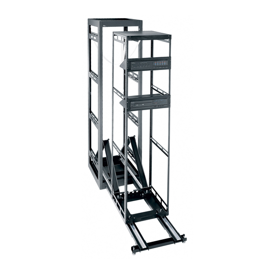
AXS/ AX-SX / SAX / SSAX
Equipment Access System
THANK YOU
Thank you for purchasing the Equipment Access System. Please read these instructions
thoroughly before installing and assembling this product.
PRODUCT FEATURES
• Allows an entire bay of heavy equipment to pull out on removable service tracks.
• Detachable rack frame allows off-site equipment integration.
• Articulating cable carriers attach to rack frame for effective cable management.
• Rolling rack frame retracts into millwork.
• Usable rack frame heights from 10 spaces (17-1/2") to 43 spaces (75-1/4") for
AX-SX & SSAX systems and 15 spaces (26-1/4") to 43 spaces (75-1/4") for
AXS and SAX systems.
• Rack frame 26" deep for AXS-xx-26, 20" deep for AXS and AX-SX systems,
16" deep for SAX & SSAX systems.
• 650 lb. capacity with proper weight distribution.
Instruction Sheet
I-1000
Rev L
Advertisement
Table of Contents

Subscribe to Our Youtube Channel
Related Manuals for Middle Atlantic Products AXS


Summary of Contents for Middle Atlantic Products AXS
- Page 1 AX-SX & SSAX systems and 15 spaces (26-1/4") to 43 spaces (75-1/4") for AXS and SAX systems. • Rack frame 26" deep for AXS-xx-26, 20" deep for AXS and AX-SX systems, 16" deep for SAX & SSAX systems. • 650 lb. capacity with proper weight distribution.
- Page 2 1) Construct rough opening and base. 2) Assemble frame. 3) Install cable carriers / rough-in pan. 4) Install service stand. 5) Attach frame to tracks and cable carriers. 6) Assemble leash. 7) Tie cable to carriers. 8) Secure rack in millwork.
- Page 3 IMPORTANT SAFETY INSTRUCTIONS • Read these instructions. WARNING: A WARNING ALERTS YOU TO A SITUATION THAT COULD RESULT IN SERIOUS PERSONAL INJURY • Keep these instructions. OR DEATH. • Heed all warnings. CAUTION: A CAUTION ALERTS YOU TO A SITUATION THAT MAY RESULT IN MINOR PERSONAL INJURY OR •...
-
Page 4: Table Of Contents
TABLE OF CONTENTS ..................Important Safety Instructions ..................Rough-In / Site Preparation ....................Millwork Specifications ..................Rough-In Pan Assembly ....................Millwork Specifications .................... Rough-In Pan Assembly ................Rough-In Pan Assembly (Continued) ...................... Rack Assembly ..................Rack Assembly (Continued) ..................Rack Assembly (Continued) ................ -
Page 5: Rough-In / Site Preparation
19-1/4” keep rack centered and protects 22-1/2” millwork. Order part # AXS-GG16, 19-1/4” AXS / AX-SX* AXS-GG20 or AXS-GG26 for 16", 20" 28-1/2” 19-1/4” AXS-xx-26* or 26" depth racks, respectively. *Setback is 1/2” for all models NOTE: When using optional gasket and guide kit, minimum rough millwork opening width is 19-5/8". -
Page 6: Millwork Specifications
36-3/16 33-1/4 37-15/16 39-11/16 36-3/4 41-7/16 38-1/2 43-3/16 40-1/4 44-15/16 46-11/16 43-3/4 48-7/16 45-1/2 50-3/16 47-1/4 51-15/16 53-11/16 50-3/4 55-7/16 AXS-XX-26 52-1/2 57-3/16 ONLY 54-1/4 58-15/16 60-11/16 57-3/4 62-7/16 59-1/2 64-3/16 61-1/4 65-15/16 67-11/16 64-3/4 69-7/16 66-1/2 71-3/16 68-1/4 72-15/16... -
Page 7: Rough-In Pan Assembly
ROUGH-IN PAN ASSEMBLY 1) Install both cable carriers to rear flange of rough-in pan using (2) 10-32 x 1/4 hex head screws per cable carrier. (FIGURE A) NOTE: Installation hardware is provided with cable carrier kit. WARNING! Cable Carriers are an integral part of this system and must be installed for the safe operation of this product to prevent the system from tipping and sliding off of tracks. -
Page 8: Rough-In Pan Assembly
ROUGH-IN PAN ASSEMBLY (CONTINUED) 2) Position rough-in pan assembly into millwork mounting platform and mount with appropriate customer-supplied hardware. (FIGURE B) NOTE: Refer to MILLWORK SPECS on page 5 for specific front setback dimensions. Mounting Locations Rough-In Millwork Pan Assembly Mounting Platform Mounting... -
Page 9: Rack Assembly
RACK ASSEMBLY 1) Align the (4) pre-installed mounting studs on each rackrail with mounting holes in top and bottom frames. (FIGURE C) 2) Loosely secure each rackrail to top and bottom frame using (2) 5/16 flange nuts per frame. (FIGURE C) Top Frame Rackrail 5/16 Flange Nuts... -
Page 10: Rack Assembly (Continued)
RACK ASSEMBLY (Continued) 3) Install (4) 10-32 Hex Head screws through top and bottom frames into each rackrail. (FIGURE D) 4) Install (2) squaring panels on front and rear of assembly using (4) 10-32 x 1/4” screws. Locate squaring panels at the mid-point of rackrail assembly. (FIGURE D) Top Frame Screws 10-32 (4 Per... -
Page 11: Rack Assembly (Continued)
4) Install service stand. To eliminate the possibility of a center bow in the 5) Attach frame to tracks and cable frame, Middle Atlantic Products suggests that the carriers. squaring panels be left in place until some of your 6) Assemble leash. -
Page 12: Service Stand / Service Track Assembly
SERVICE STAND / SERVICE TRACK ASSEMBLY 1) Assemble service stand as per instructions included with unit. 2) Adjust stand to approximate height of Notches Service rough-in pan. (FIGURE H) Tracks 3) Position notched end of each service track on service stand saddles. (FIGURE H) CAUTION! Be sure notched ends are fully seated in service stand saddles to prevent tracks from falling out. -
Page 13: Rack And Cable Carrier Installation
RACK AND CABLE CARRIER INSTALLATION 1) Place rack on service track assembly (observe proper front/rear orientation). (FIGURE K) CAUTION! Do not allow the frame to roll off end of tracks. 2) Extend and secure each cable carrier to frame using (2) 10-32 hex head screws (included in service track hardware kit). -
Page 14: Cable Management
PART # FITS of cable carrier channel. (FIGURE M) AXS-WT-25 AX-SX, SSAX AXS-WT50 AXS, SAX 4) Leave service loop at hinge point to allow for folding. NOTE: Observe and adjust for pinch points. CABLE CARRIER TIE CABLES AS SHOWN FIGURE M SECURING RACK ASSEMBLY IN MILLWORK 1) Roll loaded rack into millwork. -
Page 15: Gasket Kit (Optional) Installation
GASKET KIT (OPTIONAL) INSTALLATION 1) Remove dust and debris from rack surface with included wipes. (FIGURE P) 2) Remove paper backing from gasket and adhere gasket to bottom of rackrail. (FIGURE P) GASKET 3) Gently pull gasket up to top of rack while removing paper backing. -
Page 16: Warranty
WARRANTY Middle Atlantic Products (the "Company") warrants the Equipment Access System to be free from defects in material or workmanship under normal use and conditions for a period of (3) years from the date of shipment by the company. The Company's entire liability to the purchaser, and the purchaser's (or any other party's) sole and...
Need help?
Do you have a question about the AXS and is the answer not in the manual?
Questions and answers