Middle Atlantic Products DWR Series Instruction Sheet
Sectional wall mount rack
Hide thumbs
Also See for DWR Series:
- Instruction sheet (11 pages) ,
- Instruction sheet (13 pages) ,
- Instruction sheet (4 pages)
Table of Contents
Advertisement
Quick Links
SECTIONAL WALL MOUNT RACK
THANK YOU
Thank you for purchasing the DWR Series Sectional Wall Rack. Please read these instructions
thoroughly before installing and assembling this product.
PRODUCT FEATURES
• Tool-Free Quick-Mount
section to backpan
• Zero Clearance Latch (Optional) allows side-by-side or interior corner
mounting
• Wall mount sectional cabinet provides superior cable management
Instruction Sheet
DWR SERIES
system allows easy, one person mounting of center
TM
I-00065
Rev Q
Advertisement
Table of Contents

Related Manuals for Middle Atlantic Products DWR Series


Summary of Contents for Middle Atlantic Products DWR Series
- Page 1 Instruction Sheet DWR SERIES SECTIONAL WALL MOUNT RACK THANK YOU Thank you for purchasing the DWR Series Sectional Wall Rack. Please read these instructions thoroughly before installing and assembling this product. PRODUCT FEATURES • Tool-Free Quick-Mount system allows easy, one person mounting of center section to backpan •...
-
Page 2: Important Safety Instructions
A LICENSED PROFESSIONAL ENGINEER MUST APPROVE THE TYPE OF FASTENERS FOR THE WALL WHERE THE RACK WILL BE MOUNTED. BRACED ACCORDING TO SPECIFICATIONS SET FORTH BY LICENSED ARCHITECTS AND ENGINEERS, THE MIDDLE ATLANTIC PRODUCTS RACK/ENCLOSURE YOU PURCHASED IS CAPABLE OF SUSTAINING A PHENOMENAL LATERAL LOAD OF HIGH IMPORTANCE EQUIPMENT WITH THE FRONT RAILS FILLED TO A MAXIMUM CAPACITY OF 140 LBS. - Page 3 NOTATION SISMIQUES. UN INGÉNIEUR AGRÉÉ DOIT APPROUVER LE TYPE D'ATTACHES POUR LE MUR OÙ LA GRILLE SERA MONTÉ. HAUBANÉE SELON LES SPÉCIFICATIONS ÉNONCÉES PAR ARCHITECTES AGRÉÉS ET DES INGÉNIEURS, LA MIDDLE ATLANTIC PRODUCTS RACK / ENCEINTE VOUS AVEZ ACHETÉ EST CAPABLE DE SOUTENIR UNE CHARGE LATÉRALE PHÉNOMÉNALE DE ÉQUIPEMENT DE HAUTE IMPORTANCE AVEC LES RAILS DE FRONT REMPLIS À...
-
Page 4: Overall Dimensions
OVERALL DIMENSIONS Width: 23.4" Height: 10 RU - 35 RU Depths: 17", 22", 26"* and 32"* * Available for certain heights only INSTALLATION 1. Separate backpan from center section and determine hinge side. NOTE: DWR center section can be opened from left-to-right or vice versa depending on how backpan is installed. - Page 5 INSTALLATION (CONTINUED) 4. Remove security clips located at top and bottom of unit. (FIGURE C) PIVOT PIN 5. Remove pivot pins located at the top and bottom of backpan. (FIGURE D) SECURITY CLIP FIGURE C 6. Lift the center section and place the bottom glide strip on the edge of the backpan.
-
Page 6: Grounding And Bonding
GROUNDING AND BONDING Protective Earth Terminals (PET) are located in backpan of the wall rack. These terminals are marked with the symbol Wall rack parts, center section and door, contain or are provided with bonding points for connection to the backpan / PET. Protective earth and bonding connections shall be in accordance with Article 250 of the National Electric Code. -
Page 7: Front View
GROUNDING AND BONDING (CONTINUED) 1. Attach backpan bonding wire from 1/4”-20 backpan protective earth terminal (PET) to nearest center section bonding stud (10-32) using hardware provided. (FIGURE G) NOTE: The main protective earth ground needs to be the first terminal placed on the PET and this terminal needs to be secured on its own with a nut. -
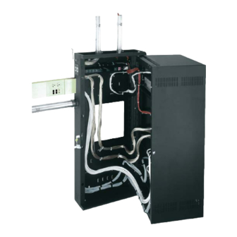
Page 8: Cable Management
CABLE MANAGEMENT • Use Hook and loop slots and/or cable ties provided on top, bottom, and sides of center section for cable management. MOUNTING WALL • Use hook and loop slots and/or cable ties in Z-bracket or cable management. BACKPAN DRESS WIRES AS SHOWN •... -
Page 9: Side View
(Only 1 power strip can be mounted to the trim.) • Power strips PD-815SC and PD-815SC-NS fit in all DWR Series racks and require only (1) clip. The clip can be installed on any trim notch. (Only 1 power strip can be mounted... - Page 10 VERTICAL POWER STRIP INSTALLATION NOTE: Requires Middle Atlantic Products part number PB-DWR (sold seperately). 1. Install PB-DWR power bracket (2 provided) to Z bracket. Z BRACKET BACKPAN SECTION SLIDE NUT PHILLIPS HEAD SCREW POWER STRIP 2. Quick clip (2 provided) for corded model strips.
- Page 11 THERMAL KNOCKOUTS BASED ON ENCLOSURE DEPTHS Thermal knockout sizes vary based on the following enclosure depths: • Enclosures 17” and 22” deep accept (2) 4” fans. (FIGURE H) • Enclosures 26” and 32” deep accept (2) 6” fans. (FIGURE J) KNOCKOUTS KNOCKOUTS FOR 4”...
-
Page 12: Warranty
Voice: 613-836-2501 - Fax: 613-836-2690 / www.middleatlantic.ca - customerservicecanada@middleatlantic.ca Factory Distribution USA: NJ - CA - IL Canada: ON - BC At Middle Atlantic Products we are always listening. Your comments are welcome. Middle Atlantic Products is an ISO 9001 and ISO 14001 Registered Company. Page 12...