Middle Atlantic Products DWR Series Instruction Sheet
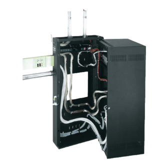
Sectional wall rack
Hide thumbs
Also See for DWR Series:
- Instruction sheet (11 pages) ,
- Instruction sheet (13 pages) ,
- Instruction sheet (4 pages)
Table of Contents
Advertisement
Quick Links
SECTIONAL WALL MOUNT RACK
THANK YOU
Thank you for purchasing the DWR Series Sectional Wall Rack. Please read these instructions
thoroughly before installing and assembling this product.
PRODUCT FEATURES
• Lever Lock™ compatible in center section and backpan for small device mounting and cable
management.
• Forward compatible for 5x faster tool-free system integration.
• Tool-free quick-mount system for easy mounting of the center section to the
backpan.
• Pivots 90º off the wall for access to rear connections.
• Zero clearance latch (optional) allows side-by-side mounting or interior
corner mounting.
Instruction Sheet
DWR SERIES
100-00030
Rev A
Advertisement
Table of Contents

Related Manuals for Middle Atlantic Products DWR Series


Summary of Contents for Middle Atlantic Products DWR Series
- Page 1 DWR SERIES SECTIONAL WALL MOUNT RACK THANK YOU Thank you for purchasing the DWR Series Sectional Wall Rack. Please read these instructions thoroughly before installing and assembling this product. PRODUCT FEATURES • Lever Lock™ compatible in center section and backpan for small device mounting and cable management.
-
Page 2: Important Safety Instructions
Braced according to specifications set forth by licensed architects and engineers, the Middle Atlantic Products rack/enclosure you purchased is capable of sustaining a phenomenal lateral load. -
Page 3: Weight Rating
Contreventé conformément aux spécifications établies par des architectes et ingénieurs agréés, le rack/boîtier Middle Atlantic Products que vous avez acheté est capable de supporter une charge latérale phénoménale. Reportez-vous aux données sismiques publiées sur la lettre sismique sur le site Web du produit Middle Atlantic. -
Page 4: Required Tools
SPEICIFICATIONS Width: 23.4” (594.4mm) Height: 10 RU - 35 RU Depth: 17” (431.8mm), 22” (558.8mm), 26” (660.4mm)*, and 32” (812.8mm)* * Available for certain heights only SUPPLIED COMPONENTS AND HARDWARE If any pieces are missing or damaged, please report it immediately to Technical Support at av.support@legrand.com or (866) 977-3901. -
Page 5: Installation
INSTALLATION CAUTION: The backpan must be installed plumb and level for proper operation. ATTENTION: La plaque profilée doit etre aplomb et de niveau pour un fonctionnement. NOTE: The backpan (A) of all DWR enclosures must be screwed to studs using the first step of this topic, except for DWRs up to 26”... - Page 6 INSTALLATION (CONTINUED) 4. Remove security clips holding pivot pins in place in the top and bottom of the backpan (A). (FIGURE C) 5. Use hand to loosen and remove top Security Clip Pivot Pin and bottom pivot pins. (FIGURE D) NOTE: Use slip joint pliers to FIGURE C carefully remove the pins, if necessary.
-
Page 7: Grounding And Bonding
GROUNDING AND BONDING Protective Earth Terminals (PET) are located in backpan of the wall rack. These terminals are marked with the symbol Wall rack parts, center section and door, contain or are provided with bonding points for connection to the backpan / PET. Protective earth and bonding connections shall be in accordance with Article 250 of the National Electric Code. -
Page 8: Cable Management
• The side of your backpan also includes knockouts for a variety of uses as shown. (FIGURE K) • Use a hammer to carefully clear any knockouts you wish to use. Middle Atlantic Products User Control Panel (UCP) Modules ⅝” UHF/VHF... - Page 9 INSTALLING POWER STRIPS Compatible Middle Atlantic Products power strips can be mounted inside the trim (C) with the included hardware. This simplifies cable management by requiring no additional accessories. NOTE: Reference which power strip models are compatible with your specific size enclosure at www.middleatlantic.com.
- Page 10 THERMAL KNOCKOUTS BASED ON ENCLOSURE DEPTHS Thermal knockout sizes vary based on the following enclosure depths: • Enclosures 17” (431.8mm) and 22” (558.8mm) deep accept (2x) 4” fans. (FIGURE L) • Enclosures 26” (660.4mm) and 32” (812.8mm) deep accept (2x) 6” fans. (FIGURE M) NOTE: Use a hammer to carefully clear any knockouts you wish to use.
-
Page 11: Warranty
WARRANTY For warranty information, refer to legrandav.com/policies/warranty_information. Corporate Headquarters P: (866) 977-3901 | F: (877) 894-6918 | legrandav.com | av.support@legrand.com Middle Atlantic Canada P: (888) 766-9770 | F: (888) 599-5009 | ca.middleatlantic.com | av.canada.customerservice@legrand.com Middle Atlantic EMEA Technical Support P: +31 495-726-003 | av.emea.middleatlantic.support@legrand.com Factory Distribution United States: New Jersey, California, and Illinois | Canada: Ontario | The Netherlands: Weert At Legrand AV Inc.