Degelman PRO-TILL 33 Operator's & Parts Manual
Hide thumbs
Also See for PRO-TILL 33:
- Operator's & parts manual (56 pages) ,
- Operator's & parts manual (50 pages)
Table of Contents
Advertisement
Quick Links
Advertisement
Table of Contents

Related Manuals for Degelman PRO-TILL 33


Summary of Contents for Degelman PRO-TILL 33
- Page 1 OPERATOR & PARTS MANUAL 143346 v1.3 D E G E L M A N I N D U S T R I E S L T D. B O X 8 3 0 - 2 7 2 I N D U S T R I A L D R I V E , R E G I N A , S K ,...
-
Page 3: Table Of Contents
OPERATORS SECTION - TABLE OF CONTENTS Introduction Safety Hook-Up Transport Transport to Field Position Field to Transport Position Operation Pre-Operation Checklist Operation Guidelines / Suggestions Setting Disc Depth Scraper Settings Service & Maintenance Maintenance Checklist Repair - Disc Maintenance Repair - Hydraulic Cylinder Repair - Bearing Components/Installation Repair - Wheel Hub PARTS SECTION - TABLE OF CONTENTS... - Page 4 IMPORTANT SAFETY REMINDER DANGER NEVER PARK, UN-HOOK, or RAISED SERVICE Pro-Till with REAR WINGS DANGER If the front hitch becomes disconnected in this position the front hitch will raise suddenly and the back of the machine will drop! Changing Discs and Servicing The best position to safely change or service the discs on the Pro-Till is when it is secured in the winged...
-
Page 5: Introduction
Degelman PRO-TILL is the fastest and most versatile piece of tillage equipment you will ever own. Use this manual as your first source of information about this machine. -
Page 6: Safety
Safety Why is SAFETY important to YOU? 3 BIG Reasons: •Accidents Can Disable and Kill •Accidents Are Costly •Accidents Can Be Avoided SAFETY ALERT SYMBOL The Safety Alert Symbol means: he Safety Alert Symbol identifies important safety messages applied to the PRO-TILL and in this ATTENTION! manual. - Page 7 GENERAL SAFETY YOU are responsible for the safe operation and 1. Read and understand the Operator’s maintenance of your Degelman PRO-TILL. Manual and all safety signs before YOU must ensure that you and anyone else who operating, maintaining or adjusting.
-
Page 8: Hook-Up
Hook-Up HOOK-UP / UNHOOKING The PRO-TILL should always be parked on a level, dry area that is free of debris and foreign objects. Follow this procedure to hook-up: 1. Clear the area of bystanders and remove foreign objects from the machine and working area. WARNING/DANGER Never disconnect 2. -
Page 9: Transport
Transport TRANSPORT SAFETY TRANSPORTING 1. Read and understand ALL the information in Use the following guidelines while transporting the the Operator’s Manual regarding procedures PRO-TILL: and SAFETY when operating the PRO-TILL in the 1. Use a safety chain and a pin with provisions for field/yard or on the road. -
Page 10: Transport To Field Position
Transport TRANSPORT TO FIELD POSITION D. With the wings fully open, extend the Transport FOLLOW PROCEDURE BELOW: Cylinders (#4) to fully lower the PRO-TILL rear A. Drive the frame sections to the ground. PRO-TILL onto level ground so it is straight behind the tractor. -
Page 11: Field To Transport Position
Transport FIELD TO TRANSPORT POSITION FOLLOW PROCEDURE BELOW: A. Fully extend the Wheel and Roller Cylinders C. Retract the Wing Cylinders (#3), bringing both (#1 & #2), to completely raise the disc frames. wings inward towards the frame. NOTE It is important to fully raise the disc frames up as high as possible as it puts the rollers and wheels in the correct position for low transport. -
Page 12: Operation
Operation OPERATING SAFETY PRE-OPERATION CHECKLIST 1. Read and understand the Operator’s Manual It is important for both personal safety and maintaining and all safety signs before using. good operational condition of the machine that the pre- operational checklist be followed. 2. - Page 13 Operation OPERATING GUIDELINES 1. Place both the Transport Cylinders (#4) and the Wing Cylinders (#3) into the FLOAT position before operation. IMPORTANT Transport Cylinders and Wing Cylinders MUST both be in the FLOAT position for the PRO-TILL to contour properly and to avoid possible cylinder or equipment damage.
-
Page 14: Setting Disc Depth
Operation SETTING DISC DEPTH - FRONT AND REAR Front Disc Depth Rear Disc Depth Adjustment Adjustment Spacer Storage 1/2” Spacer Storage Typically Typically Set to 2” Set to 2” Adjusting the cutting depth of the front and rear Use the following as a guideline for setting depth: discs is accomplished by adding or removing a number of 1/4”... - Page 15 Operation SCRAPER POSITIONS ADJUSTING SCRAPER PLATE DEPTH Engaged Disengaged NOTE: As the Disengaged scraper plates Engaged Bolt Pivot Bolt Pivot Bolt Scraper Bolt Position Position wear with usage Plate they will need to be adjusted Engaged Position accordingly. Adjustment Bolt Scraper Plate SETTING SCRAPER POSITION...
-
Page 16: Service & Maintenance
143198 - Decal, Degelman - 8-1/4” unit is on level ground in the proper transport or field position. 142961 - Decal, Pro-Till 33 - 4” 142962 - Decal, Pro-Till 33 - 7” 142949 - Decal, Pro-Till 40 - 4” 142950 - Decal, Pro-Till 40 - 7”... -
Page 17: Maintenance Checklist
Service & Maintenance MAINTENANCE CHECKLIST SERVICE After reviewing the Maintenance and Hydraulic GREASING Safety Information, use the Maintenance Checklist Grease: Use an SAE multipurpose grease with provided for regular service intervals and keep a extreme pressure (EP) performance. Also acceptable record of all scheduled maintenance: is an SAE multipurpose lithium. - Page 18 Service & Maintenance TORQUE SPECIFICATIONS CHECKING BOLT TORQUE WHEEL NUT & WHEEL BOLT TORQUE The tables shown below give correct torque values Wheel Nut/Bolt Torque for various bolts and capscrews. Tighten all bolts to Size lb.ft (N.m) the torques specified in chart unless otherwise noted. 280-300 (380-405) Check tightness of bolts periodically, using bolt torque chart as a guide.
- Page 19 Service & Maintenance HYDRAULIC CYLINDER REPAIR When cylinder repair is required, clean off unit, disconnect hoses and plug ports before removing cylinder. NOTE: Complete rebuilt cylinders may be available. Contact your dealer for further information. COMMON DEGELMAN CYLINDER COMPONENTS Lock Barrel...
- Page 20 Service & Maintenance WHEEL HUB REPAIR COMMON HUB & SPINDLE COMPONENTS Dust Inner Inner Flat Seal Cone Spindle Washer Outer Outer Slotted Dust Cone Nut & Cotter Pin IMPORTANT Be sure to block up unit securely before removing tires. DISASSEMBLY ASSEMBLY 1.
-
Page 21: Pro-Till Section Overview
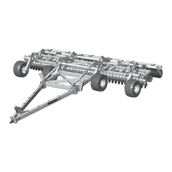
Pro-Till Overview RH Wheel Exploded Overview of a 40’ Pro-Till Strut Wing Roller Frame RH Wing Front Frame Hitch Cage Roller Hitch Pole Center Legs Frame Scraper - or - Hyd Jack RH Wing Assembly Disc Gangs Hitch Pole Center Frame Roller Frame... -
Page 22: Hitch Pole Frame Components
780278 - Hose Clamp - 2 Halves (11) 572550 - Hitch Pole Frame Assembly (1) 143198 - Decal, Degelman - 8-1/4” (1) 117145 - Bushing (2) 572730 - Pin, 1-15/16 (2) mounts with... 118024 - Bolt, 5/8 x 1-1/2 (2) - Page 23 572575 - Pole Leg Assembly - RH (1) 572576 - Pole Leg Assembly - LH (1) 142950 - Decal, Pro-Till 40 - 7” (2) (142962 - Decal, Pro-Till 33 - 7”) 117565 - Bolt, 1 x 4-1/2 UNC GR8 (28) 131020 - Flat washer,...
-
Page 24: Wheel & Rockshaft Components
117145 - 118062 - Bolt, 3/4 142949 - Decal, Pro-Till 40 - 4” (1) Bushing (1) x 5-1/2 GR8 (4) (142961 - Decal, Pro-Till 33 - 4”) 117414 - Lock Nut, 3/4 LH Wheelstrut GRC Unitorque (4) Components 123590 - LH... -
Page 25: Center & Wing Frame Components
Roller Cylinder (2) components & 117145 - Bushing (2) c/w Wings & Center Section installation details) Scrapers Scraper Option 142008 - Decal, Degelman 6” (1) 572665 - Roller Frame Assembly, Center (1) 118447 - Lock Nut, 131815 - Rubber 5/8 Unitorque (8) - Page 26 Wing Frame Components Pro-Till 33’ (10m) Wing Frame Components (LH Shown) 572730 - Pin, 1-15/16 118537 - Flat washer, 5/8 - F436 (2) x 10-1/4 (2) 118508 - Lock Washer, 5/8 (2) 118024 - Bolt, 5/8 x 1-1/2 (2) 123540 - Wing Cylinder (1) 122883 - Cylinder Depth Stop Block - 1/4”...
- Page 27 Wing Frame Components Pro-Till 40’ (12m) Wing Frame Components 572730 - Pin, 1-15/16 x 10-1/4 (2) (LH Shown) 118024 - Bolt, 5/8 x 1-1/2 (2) 123540 - Wing 118508 - Lock Washer, 5/8 (2) Cylinder (1) 118537 - Flat washer, 5/8 - F436 (2) 122883 - Cylinder Depth Stop Block - 1/4”...
-
Page 28: Scraper Kit Components
Scraper Kit Components 572819 - Scraper Option Kit for 10M/33’ (1) 572824 - Scraper Option Kit for 12M/40’ (1) Scrapers Sections for 10M/33’ Kit Scrapers Sections for 12M/40’ Kit Center Section 572826 - 15 Section (1) & 572825 - 16 Section (1) Center &... - Page 29 Scraper Kit Components Initial Scraper Bracket Adjustment Scraper Positions Overview - Loosen scraper bracket U-bolts. - Adjust bracket position to align scraper bars to center of rubber roller grooves. - Re-tighten U-bolts. Re-check after use. Pivot Bolt Scraper Positioning Adjust Position U-bolts Bracket Bolt...
-
Page 30: Roller Assembly Components
Rubber Roller Components 3m Roller 131729 - Roller Assembly Components 131722 - Axle Lock Nut (2) 131716 - Axle 131723 - Axle Key (2) Lock Washer (2) 131730 - Tube Assembly (1) 131712 - End Plate (2) 131717 - End Axle Shaft (2) 131725 - Washer, Roller End Plate (12) 117572 - Bolt, M14 x 50 - 10.9 (12) 131714 - Roller... -
Page 31: Cylinders
Hydraulic Cylinders MASTER CYLINDER WITH SPACER STOP 123572 - Barrel (1) 123570 - Cylinder, 4-1/2” x 8” x 2” 123586 - Lock Ring (1) 123269 - Lock nut, 1” UNF GR5 Unitorque (1) 123584 - Open Cap (1) 123299 - Piston, Unitised (1) 123578 - Rod &... - Page 32 Disc Gang Assembly Locations Pro-Till 33’ (10m) Disc Gang Assembly Mounting (20) Smaller RH Wing Disc End Discs 118935 - Bolt, 5/8 x 2-1/2 GR8 (4) Gang Sections 572704 - V-Clamp (1) 572517 - Shim, V-Clamp (2) 118447 - Lock Nut, 5/8...
-
Page 33: Disc Gang Assembly Components
Disc Gang Assembly Components Pro-Till 33’ (10m) 572776 - Disc Gang Assembly, 572775 - Disc Gang Assembly, Front - LH - 3m Front - RH - 3m 10 - Standard 20” Front Disc Assemblies 11 - Standard 20” Front Disc Assemblies 1 - Smaller 18”... - Page 34 Disc Gang Assembly Locations Pro-Till 40’ (12m) Disc Gang Assembly Sections Overview Disc Gang Assembly Mounting (24) 118935 - Bolt, 5/8 x 2-1/2 GR8 (4) 572704 - V-Clamp (1) 572517 - Shim, V-Clamp (2) 118447 - Lock Nut, 5/8 GRC Unitorque (4) NOTE: Using the 4 Bolt Tightening...
- Page 35 Disc Gang Assembly Components Pro-Till 40’ (12m) 572717 - Disc Gang Assembly, 572718 - Disc Gang Assembly, 143550 - Disc, Front - Standard Section Front - Short Section 18” (1) 14 - Standard 20” Front Disc Assemblies 16 - Standard 20” Front Disc Assemblies 1 - Smaller 18”...
- Page 36 Hydraulic Layout - 1 - Wheels Pro-Till 33’ (10m) Hydraulic Fittings Required 141581 - Quick Coupler-m - 3/4 ORB 141515 - Connector, 3/4 JIC-m x ORB 142952 - Label, Relief - Wheels #1 (1) 141504 - Elbow, 90º 3/4 JIC-m x ORB m 141505 - Tee, 3/4 JIC M x M x 3/4 ORB M 141518 - 90°...
- Page 37 Hydraulic Layout - 1 - Wheels Pro-Till 40’ (12m) Hydraulic Fittings Required 141581 - Quick Coupler-m - 3/4 ORB 141515 - Connector, 3/4 JIC-m x ORB 142952 - Label, Relief - Wheels #1 (1) 141504 - Elbow, 90º 3/4 JIC m x ORB m 141505 - Tee, 3/4 JIC M x M x 3/4 ORB M 141518 - 90°...
- Page 38 Hydraulic Layout - 2 - Rollers Pro-Till 33’ (10m) Hydraulic Fittings Required 141581 - Quick Coupler-m - 3/4 ORB 141515 - Connector, 3/4 JIC-m x ORB 142954 - Label, Relief - Packers #2 (1) 141504 - Elbow, 90º 3/4 JIC m x ORB m 141505 - Tee, 3/4 JIC M x M x 3/4 ORB M 141518 - 90°...
- Page 39 Hydraulic Layout - 2 - Rollers Pro-Till 40’ (12m) Hydraulic Fittings Required 141581 - Quick Coupler-m - 3/4 ORB 141515 - Connector, 3/4 JIC-m x ORB 142954 - Label, Relief - Packers #2 (1) 141504 - Elbow, 90º 3/4 JIC m x ORB m 141505 - Tee, 3/4 JIC M x M x 3/4 ORB M 141518 - 90°...
- Page 40 Hydraulic Layout - 3 - Wings Hydraulic Fittings Required 141581 - Quick Coupler-m - 3/4 ORB 141515 - Connector, 3/4 JIC-m x ORB 142956 - Label, Relief - Wings #3 (1) 141504 - Elbow, 90º 3/4 JIC m x ORB m 141505 - Tee, 3/4 JIC M x M x 3/4 ORB M 141518 - 90°...
- Page 41 Hydraulic Layout - 4 - Transport Hydraulic Fittings Required 141581 - Quick Coupler-m - 3/4 ORB 141515 - Connector, 3/4 JIC-m x ORB 142957 - Label, Pressure - Transport #4 (1) 141504 - Elbow, 90º 3/4 JIC m x ORB m 141505 - Tee, 3/4 JIC M x M x 3/4 ORB M 141518 - 90°...
- Page 42 Hydraulic Layout - 5 - Jack Hydraulic Fittings Required 141581 - Quick Coupler-m - 3/4 ORB 142960 - Label, Relief - Jack #5 (1) 141515 - Connector, 3/4 JIC-m x ORB 141504 - Elbow, 90º 3/4 JIC m x ORB m 141595 - Dual Check Valve - #8 ORB 142959 - Label, Pressure - Jack #5 (1) 141609 - Adaptor, 3/4 JIC - 1/16 Orifice...
- Page 43 Light Routing Rear Light Configuration & Components Wire Harness - w/plugs (1) 572785 - Pro-Till, Wire Harness 244591 - Dual Lamp (1) 244590 - Dual Lamp (1) BRACKET INSTALLATION GUIDELINE 1. Position the Adapter Brackets and LH/RH 3. Connect and properly position the electrical Light Brackets loosely in place with hardware.
-
Page 44: Warranty
Re-torque of fastening hardware, Hydraulic fluid purities, drive train alignments, and clutch operation) 3. If parts not made or supplied by Degelman have been used in the connection with the unit, if, in the sole judgement of Degelman such use affects its performance, safety, stability or reliability. -
Page 45: B O X
It is the retail customer’s responsibility to deliver the product to the authorized Degelman dealer, from whom he purchased it, for service or replacement of defective parts, which are covered by warranty. Repairs to be submitted for warranty consideration must be made within forty-five days of failure.
Need help?
Do you have a question about the PRO-TILL 33 and is the answer not in the manual?
Questions and answers