Degelman PRO-TILL 40 Operator's & Parts Manual
Hide thumbs
Also See for PRO-TILL 40:
- Operator's & parts manual (56 pages) ,
- Quick start manual (2 pages) ,
- Operator's & parts manual (50 pages)
Table of Contents
Advertisement
Quick Links
OPERATOR & PARTS
MANUAL
143437 v1.0
PRO-TILL 40
D E G E L M A N
I N D U S T R I E S
L P
B O X
8 3 0 - 2 7 2
I N D U S T R I A L
D R I V E ,
Serial Numbers: 6715 and above
R E G I N A ,
S K ,
C A N A D A ,
S 4 P
3 B 1
F A X 3 0 6 . 5 4 3 . 2 1 4 0
P H 3 0 6 . 5 4 3 . 4 4 4 7
1 . 8 0 0 . 6 6 7 . 3 5 4 5
D E G E L M A N . C O M
Advertisement
Table of Contents

Subscribe to Our Youtube Channel
Related Manuals for Degelman PRO-TILL 40


Summary of Contents for Degelman PRO-TILL 40
- Page 1 OPERATOR & PARTS MANUAL 143437 v1.0 PRO-TILL 40 D E G E L M A N I N D U S T R I E S B O X 8 3 0 - 2 7 2 I N D U S T R I A L...
- Page 3 QUICK-START GUIDE WARRANTY PRO-TILL 40 REMEMBER! You must complete Product * Refer to operators manual for complete safety and operation info. Registration to be eligible for Warranty. Connect Hydraulics WHEELS CONSTANT PRESSURE FLOAT ROLLERS TRANSPORT WINGS JACK IMPORTANT: The Wing Cylinder Circuit includes a Down Pressure Valve.
- Page 4 Loosen the 4 bolts to rotate downward. Set the scraper MAX Transport Speed: 40 km/h (25 MPH) clearance Set Gap (1/4” to 3/8”). distance at Properly tighten. 1/4” to 3/8” from roller surface. PRO-TILL 40 © 2024 Degelman Industries LP...
-
Page 5: Table Of Contents
* Reference Sheet Quick-Start Guide / Unloading Instructions OPERATORS SECTION - TABLE OF CONTENTS IMPORTANT Safety Notice Introduction Safety Hook-Up Transport Transport to Field Position Field to Transport Position Operation Pre-Operation Checklist Operation Guidelines / Suggestions Setting Disc Depth Scraper Settings Adjustments: Rephasing Cylinders Adjustments: Wing Down Pressure Troubleshooting... - Page 6 IMPORTANT SAFETY REMINDER DANGER NEVER PARK, UNHOOK, or RAISED SERVICE Pro-Till with REAR WINGS DANGER If the front hitch becomes disconnected in this position the front hitch will raise suddenly and the back of the machine will drop! CHANGING DISCS AND SERVICING The best position to safely change or service the discs on the Pro-Till is when it is secured in the winged...
-
Page 7: Introduction
Degelman Pro-Till is the fastest and most versatile piece of tillage equipment you will ever own. Use this manual as your first source of information about this machine. -
Page 8: Safety
CAUTION: Indicates a potentially hazardous situation CAUTION that, if not avoided, MAY result in minor or moderate injury if proper practices are not taken, or, serves as a reminder to follow appropriate safety practices. 143437 - PRO-TILL 40 (14-June-2024) - Page 9 • Do not modify the equipment in any way. Unauthorized modification may impair the function and/or safety and could affect the life of the equipment. • Think SAFETY! Work SAFELY! 143437 - PRO-TILL 40 (14-June-2024)
-
Page 10: Hook-Up
8. Install a safety chain between the tractor and the hitch. 9. Connect lights (electrical socket plug) to tractor. 10. Raise the hydraulic hitch jack. 11. When unhooking from the tractor, reverse the above procedure. 143437 - PRO-TILL 40 (14-June-2024) -
Page 11: Transport
40km/hr, the centre frame wheels (transport tires) must be checked and properly inflated: 94 PSI (648 kPa). IMPORTANT Under NO CIRCUMSTANCES should there RIDERS ever be riders while the Pro-Till is in transport. 143437 - PRO-TILL 40 (14-June-2024) -
Page 12: Transport To Field Position
This will ensure constant down pressure is applied to the wings and the machine can still contour over uneven terrain effectively. (Refer to your tractor's manual for proper procedures.) 143437 - PRO-TILL 40 (14-June-2024) -
Page 13: Field To Transport Position
E. With the wings in the proper position, retract Lift rear sections using the Transport the Transport Cylinders (#3) fully lowering the Cylinders (3), then fold the wings forward wings onto the wing transport carriers. using the Wing Cylinders (4). 143437 - PRO-TILL 40 (14-June-2024) -
Page 14: Operation
If excessive 1. Check all hardware. Tighten as required. disc wear is evident, replacement may be 2. Check all hydraulic system connections. required. Refer to maintenance section. Tighten if any are leaking. 143437 - PRO-TILL 40 (14-June-2024) -
Page 15: Operation Guidelines / Suggestions
RH WING 2" adjust the cutting depth by raising/lowering the front Intitial Distance or rear sets of discs by following the guidelines in the settings for Wing “Setting Disc Depth” section. Wheel Cylinder Adjustment Lugs. 143437 - PRO-TILL 40 (14-June-2024) -
Page 16: Setting Disc Depth
1/2” you want to Raise it. NOTE: As the discs wear with usage, the disc depth 7. Repeat above procedure until proper depth is settings will also need to be adjusted accordingly. achieved. -10- 143437 - PRO-TILL 40 (14-June-2024) -
Page 17: Scraper Settings
Double Sided Scraper Blades Note: When blades are being reversed, the complete section must be changed at the same time or adjustment will not work properly. -11- 143437 - PRO-TILL 40 (14-June-2024) -
Page 18: Adjustments: Rephasing Cylinders
Once the air has been up in the circuit. pushed out of the system the reservoir can become low. This can introduce air into the system again. -12- 143437 - PRO-TILL 40 (14-June-2024) -
Page 19: Adjustments: Wing Down Pressure
Re-tighten lock nut. Note: Future adjustment of this screw may be necessary for different field conditions and working depths. -13- 143437 - PRO-TILL 40 (14-June-2024) -
Page 20: Troubleshooting
- Lower the flow on the wing circuit hydraulic remote. (Please refer to the Tractor's Operators Manual) - If plugging persists wait for soil conditions to dry out even more. -14- 143437 - PRO-TILL 40 (14-June-2024) - Page 21 - Pre-work heavy trash or wet areas at a slower speed (Recommended practice) & at a different angle than final pass. - Wait for soil conditions to dry out more. - Ensure the wing circuit hydraulic remote is constantly engaged in the extended direction. -15- 143437 - PRO-TILL 40 (14-June-2024)
-
Page 22: Service & Maintenance
Only disconnect when unit is on level ground in the proper transport or field position. IMPORTANT: Safely secure Pro-Till in winged forward transport position when changing or servicing discs. -16- 143437 - PRO-TILL 40 (14-June-2024) -
Page 23: Repair - Wheel Hub
4. If applicable, install Rear Locknuts using Wheel Dust Cap Torque Values. 9. Fill dust cap half full of grease and gently tap into position. 10. Pump grease into hub through grease fitting until lubricant can be seen from dust seal. -17- 143437 - PRO-TILL 40 (14-June-2024) - Page 24 5. Ensure hoses are properly clamped and secured in 915 (1240) 1310 (1780) position after routing is complete to provide a cleaner 1250 (1695) 1785 (2420) installation and prevent possible damage or hazards. 1600 (2175) 2290 (3110) v1.1 -18- 143437 - PRO-TILL 40 (14-June-2024)
- Page 25 2. Align, thread into place and hand tighten. 8. Inspect to ensure that O-ring is not pinched and that washer is seated fl at on the face of the port. 3. Tighten to proper torque from the table shown above. -19- 143437 - PRO-TILL 40 (14-June-2024)
-
Page 26: Repair - Hydraulic Cylinder
5. Apply Loctite anti-seize before installing cylinder end cap. 6. Torque cylinder end cap to 440 lb.ft (600 N.m). 7. Tighten Set Screw on end cap to 6 lb.ft (8 N.m). -20- 143437 - PRO-TILL 40 (14-June-2024) - Page 27 142008 - Decal, Degelman - 6” 143198 - Decal, Degelman - 8-1/4” IMPORTANT: DO NOT 142949 - Decal, Pro-Till 40 - 4” use oil or grease on pins or 142950 - Decal, Pro-Till 40 - 7” bushing surfaces when re-installing.
- Page 28 -22- 143437 - PRO-TILL 40 (14-June-2024)
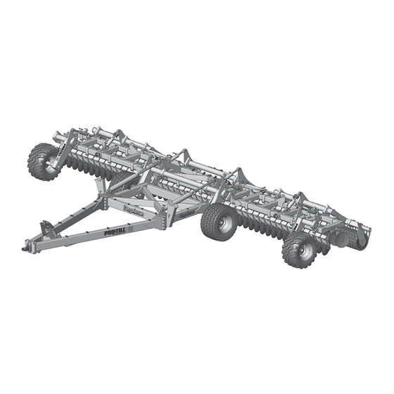
- Page 29 Pro-Till Overview Exploded Overview of a Pro-Till 40 RH Wheel Strut RH Wing Frame Wing Roller Frame Hyd Jack Assembly Wheel Rockshaft Center Front Cage Frame Hitch Pole Roller Hitch Legs - or - RH Wing Disc Gangs Hitch Pole...
-
Page 30: Hitch Pole & Front Frame Components
118123 - Bolt, 1/4 x 1 (2) 118483 - Lock Nut, 1/4 - Unitorque (2) 142008 - Decal, Degelman - 6” (2) (See electrical wire routing 142557 - Decal, Reflector page for light components) Amber - 2 x 9 (2) -24- 143437 - PRO-TILL 40 (14-June-2024) - Page 31 572578 - Front Hitch Assembly CAT 5 (1) 124043 - Front 124041 - Ball 142950 - Decal, Hitch (1) c/w Insert, to 2" (1) Pro-Till 40 - 7” (2) 124047 - Ball, 2-3/4” (1) 572573 117565 - Bolt, 1 x OPTIONAL:...
-
Page 32: Wheel & Rockshaft Components
572655 - Wheel Strut Depth Cylinders (2) Assembly - RH (1) 118062 - Bolt, 3/4 117145 - 142949 - Decal, Pro-Till 40 - 4” (1) x 5-1/2 GR8 (4) Bushing (1) 117414 - Lock Nut, 3/4 LH Wheel Strut GRC Unitorque (4) -
Page 33: Center & Wing Frame Components
572786 - Spacer, Bushing (2) 117171 - Bearing Unit, 4 Hole (2) IMPORTANT: Setscrew MAX Torque is 30 lb . ft (41 N . m). 117172 - Bearing Insert, 2-7/16 (1) Do not over-torque. -27- 143437 - PRO-TILL 40 (14-June-2024) - Page 34 572786 - Spacer, Bushing (2) 117171 - Bearing Unit, 4 Hole (2) IMPORTANT: Setscrew MAX Torque is 30 lb . ft (41 N . m). 117172 - Bearing Insert, 2-7/16 (1) Do not over-torque. -28- 143437 - PRO-TILL 40 (14-June-2024)
-
Page 35: Roller Assembly Components
117581 - TopLock Nut, 5/8 Flanged (2) are achieved. Note: Setting too low can 117460 - Bolt, CRG 5/8 x 3 GR8 (2) result in a trench or possibly cause plugging. 118447 - Lock Nut, 5/8 Unitorque (2) -29- 143437 - PRO-TILL 40 (14-June-2024) -
Page 36: Scraper Components
ProTill 40 Kit: 572653 (Set of 93) 572957 - Scraper Blade, Max-Life - 1/4 Install 118186 - Bolt, 1/2 x 1-1/4 GR8 Wear with Wear 118729 - Lock Nut, 1/2 Unitorque Edge down Surface down -30- 143437 - PRO-TILL 40 (14-June-2024) -
Page 37: Disc Gang Assembly & Components
1-1/2". This should be STEP 1 the standard distance between all gang sections. 20" Discs A = 8-5/8" 1-1/2" STEP 2 B = 5" -OR- 22" Discs A = 8-5/8" B = 4-1/2" -31- 143437 - PRO-TILL 40 (14-June-2024) -
Page 38: Disc Arm Components & Disc Options
20” Notched 20” Straight 20” Notched 22” Straight 22” Notched end disc sizes and locations for customer Notched Notched preferred performance in certain soil or 143567 143568 143556 143557 143553 143562 143563 143566 field conditions.) -32- 143437 - PRO-TILL 40 (14-June-2024) -
Page 39: Hydraulic Cylinders
Note the Cylinder Pin (Note: Factory height setting of the threaded bushing / Orientation bolt plate bushing distance is set by using the stack of depth plates and a gap clearance of less than 1/32") -33- 143437 - PRO-TILL 40 (14-June-2024) -
Page 40: Hydraulic Routing
123052 - Cylinder, 123052 - Cylinder, 3-3/4 x 8 x 2 (1) 3-3/4 x 8 x 2 (1) 123045 - Cylinder, (Seal Kit: 123051) (Seal Kit: 123051) 4-1/4 x 8 x 2 (1) (Seal Kit: 123046) -34- 143437 - PRO-TILL 40 (14-June-2024) - Page 41 4-1/4 x 8 x 2 (1) 3-3/4 x 8 x 2 (1) 4-1/4 x 8 x 2 (1) (Seal Kit: 123046) (Seal Kit: 123051) (Seal Kit: 123046) Previous Shown Refer to detail images above for current layouts. -35- 143437 - PRO-TILL 40 (14-June-2024)
- Page 42 126490 - Hose, 3/8 x 312 (1) 126489 - Hose, 3/8 x 264 (1) 126488 - Hose, 3/8 x 192 (1) 126483 - Hose, 3/8 x 110 (1) 123048 - Cylinder, 5-1/2 x 42 x 2-1/2 (2) (Seal Kit: 123047) -36- 143437 - PRO-TILL 40 (14-June-2024)
- Page 43 118511 - Flat Washer, 3/8 (2) 118417 - Lock 117416 - Lock Nut, 3/8 (2) Nut, 7/8 GRC Unitorque (2) 117474 - Bolt, 7/8 x 4 GR8 (2) 118774 - Flat Washer, 7/8 (4) -37- 143437 - PRO-TILL 40 (14-June-2024)
- Page 44 126483 - Hose, 3/8 x 110 (1) 126484 - Hose, 3/8 x 120 (1) Open IMPORTANT: Close the ball valve to prevent accidental Ball Closed operation of this Valve circuit. Ensure ball Closed valve handle remains Position in closed position. -38- 143437 - PRO-TILL 40 (14-June-2024)
-
Page 45: Dirt Deflector Components & Adjustments
- Loosen the two deflector adjustment bolts - Fully raise the deflector plate to the top of the adjustment slot. - Then retighten the bolts. Optional: The Dirt Deflector Assembly may be removed & stored. -39- 143437 - PRO-TILL 40 (14-June-2024) -
Page 46: Light Electrical Routing & Components
Wire Harness - w/plugs (1) 572782 - Pro-Till, Wire Harness 129125 - Dual Lamp, LH (1) 129126 - Dual Lamp, RH (1) 129127 - 129127 - Single Single Amber Amber Lamp (2) Lamp (2) -40- 143437 - PRO-TILL 40 (14-June-2024) - Page 47 142650 - Decal, Fluorescent - 2 x 9 (2) 118768 - Bolt, 7/8 x 3-1/2 (2) -RH side 117474 - Bolt, 7/8 x 4 GR8 (2) -LH side Note: Uses longer bolts on LH where Wing Pressure Bracket is also installed. -41- 143437 - PRO-TILL 40 (14-June-2024)
-
Page 48: Warranty
Re-torque of fastening hardware, Hydraulic fluid purities, drive train alignments, and clutch operation) 3. If parts not made or supplied by Degelman have been used in the connection with the unit, if, in the sole judgement of Degelman such use affects its performance, safety, stability or reliability. -
Page 49: B O X
It is the retail customer’s responsibility to deliver the product to the authorized Degelman dealer, from whom he purchased it, for service or replacement of defective parts, which are covered by warranty. Repairs to be submitted for warranty consideration must be made within forty-five days of failure.
Need help?
Do you have a question about the PRO-TILL 40 and is the answer not in the manual?
Questions and answers