Table of Contents
Advertisement
Quick Links
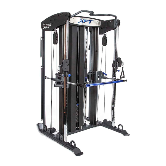
XFT STRENGTH TR INING SYSTEM
Owners Manual
Record your Product Registration Info here:
S E R I A L
1 2 3 4 5 6 7 8
Serial Number:__________________________
Purchase Date:__________________________
Open your Camera
Dealer Name:___________________________
App, point it at the
QR Code
click the
Register your product at
www.bodycraft.com,
link for additional
information.
then click the link at the top of the page.
Serial Number Location
Advertisement
Table of Contents

Subscribe to Our Youtube Channel
Related Manuals for BodyCraft XFT


Summary of Contents for BodyCraft XFT
- Page 1 XFT STRENGTH TR INING SYSTEM Owners Manual Record your Product Registration Info here: S E R I A L 1 2 3 4 5 6 7 8 Serial Number:__________________________ Purchase Date:__________________________ Open your Camera Dealer Name:___________________________ App, point it at the...
- Page 3 Congratulations and Welcome to the BODYCRAFT Family Thank you for selecting a BODYCRAFT XFT Strength Training System. Your choice reflects a wise investment for you and your family (or facility). We hope you use it for many healthy years BODYCR FT offers a complete array of high-quality fitness equipment. Please refer to our website at www.bodycraft.com to view more ways to enhance your lifestyle.
-
Page 4: Table Of Contents
ABLE ONTENTS PRODUCT SAFETY SPECIFICATIONS TOOLS NEEDED XFT PARTS LIST PRODUCT ASSEMBLY 6-23 DETAILED PARTS LISTS 24-27 OVERVIEW (EXPLODED DRAWING) INSPECTION MAINTENANCE WARRANTY PRODUCT USE / CALL-OUTS For easy to read complete assembly step-by-step in full color go directly to... -
Page 5: Product Safety
It is imperative that you retain this Assembly Instructions and be sure all warning labels are legible and intact. Replacement Assembly Instructions and labels are available from BODYCRAFT. If you are unsure about the proper use of the BODYCRAFT strength machine call your local BODYCRAFT dealer or our Customer Service Department. 800-990-5556 or support@bodycraft.com... -
Page 6: Specifications Tools Needed
PECIFICATIONS OOLS EEDED HEIGHT Recommended Important Notes and Tips: Tools 1. Do not tighten bolts until instructed. for Assembly 2. Two people are required for the safe assembly of this product. Ratchet 3. Use silicone lubricant on the weight stack guide 9/16 Socket rods prior to weight plate installation. -
Page 7: Xft Parts List
XFT PARTS LIST NOTE: If you are missing a listed part, it likely has been pre-installed in our factory for quality control purposes. Please continue with assembly. (1) BASE FRAME (2R) RIGHT BASE LEG (3L) LEFT BASE LEG (4) HOLLOW... - Page 8 XFT PARTS LIST NOTE: If you are missing a listed part, it likely has been pre-installed in our factory for quality control purposes. Please continue with assembly. (14) CHIN-UP BAR (13) TOP FRAME (15) CONNECTOR FRAME (17) TOP GUIDE ROD HOLDER...
- Page 9 XFT PARTS LIST NOTE: If you are missing a listed part, it likely has been pre-installed in our factory for quality control purposes. Please continue with assembly. (52) 90mm (51) 114mm (60) SELECTOR PIN PULLEY PULLEY X 33pcs X 3pcs...
-
Page 10: Product Assembly
Product Assembly STEP To ease the assembly process, do not tighten bolts until told to do so. 1. Attach the Right Left Base Legs (2R 3L) to the Base Frame (1) using four 1/2” X 1” Hex Threaded Bolts (93), four 1/2” Washers (120), four 3/8” X 3/4” Hex Threaded Bolt (101) and four 3/8”... - Page 11 Product Assembly STEP To ease the assembly process, do not tighten bolts until told to do so. 1. REMOVE the PACKING BOLT ( A ) and WASHER ( B ) that secure the Counter Weight/Cable Assembly to the bottom of BOTH of the MAIN UPRIGHT FRAMES (5). Note: The 2 MAIN UPRIGHT (5) is not shown below.
- Page 12 Product Assembly STEP To ease the assembly process, do not tighten bolts until told to do so. Fig. 1 Fig. 2 SLIDE 1. Please confirm that the 2 Packing Bolt ( A ) and Washer ( B ) have been removed from the bottom of the Main Upright Frame (5).
- Page 13 Product Assembly STEP To ease the assembly process, do not tighten bolts until told to do so. Fig. 1 Fig. 2 1. Attach the Top Frame (13) to the Main Upright Frames (5) by first routing each of the Counter Weight Cables (131) up through the outer pulley holders as shown in Fig.
- Page 14 Product Assembly STEP This Step requires a ceiling height of 95”. NOTE: Review the diagram below For low height installations, skip this to familiarize yourself with the page and continue to the next page. various components and terms. 1. Refer to Fig. 2. Begin the installation of the Solid Linear Guide Rods (11) by first sliding a 48mm Rubber Upper Cushion (75) onto the upper portion of the rod.
- Page 15 Product Assembly STEP This step is for low ceiling height installations 84.5” If you completed Step 5 on the previous page, skip this page and continue to the next. Plates Remove the two Linear Bearing Cartridges by removing eight M6 X 12L Round Screw (109) and eight M6 Washers (124) from the Connector Frame (15).
- Page 16 Product Assembly STEP To ease the assembly process, do not tighten bolts until told to do so. 1. Loosely attach Front Right Front Left Upright Frames 8L) to the Right Left Base Legs 3L) using four 3/8” Washers (118), four 3/8”...
- Page 17 Product Assembly STEP To ease the assembly process, do not tighten bolts until told to do so. 1. Slide the Right Left Pulley Height Adjusters (19R 20L) with the number gauge opening facing inward, onto the Right Left Cable Adjusting Upright Frame (7R 8L) as shown by pulling the pop-pin.
- Page 18 Product Assembly STEP If you have 19 Weight Plates, DO NOT install the two Stack Spacers (24), See figures 1 1. Assembly the Top Plate (38) to the the Selector Stem (40) using one Top Plate Bolt (103). TIGHTEN the Top Plate Bolt (103) at this time. 2.
- Page 19 Product Assembly STEP 200lb Stack 150lb Stack Fig 1. Fig 2. 19 Weight Plates 14 Weight Plates Slight Angle...
- Page 20 Product Assembly STEP To ease the assembly process, do not tighten bolts until told to do so. 1. Attach the Adjustment Lever (25) and Axle (66) to the Adjuster Frame (24) using three M5 X 25L Screws (112), six M5 Washers (126) and three M5 Nylon Nuts (135).
- Page 21 Product Assembly STEP For this step, be aware that when pulling down on the Bolt WARNING End of the Counter Weight Cable, it is heavy. It is required that someone assist by holding the cable during assembly. 1. Attach each of the Bolts Ends of the pre-installed Counter Weight Cables onto the Right Left side of the Steel Plates (44) by pulling the cable down by the Bolt end located just below the Top Frame.
- Page 22 Product Assembly STEP TOP CABLE (56) Steel Ball End Bolt End NOTE: It is recommend that you study the cable routing overview beginning with T1 before following the steps below. 1. Refer to Fig T1. Screw the Bolt End of the Top Cable (56) into the Adjuster Frame (24). 2.
- Page 23 Product Assembly STEP TOP CABLE (56) Steel Ball End Bolt End T5,T11 T3,T6 Bolt End T7,T9,T10 Cable Routing Overview T19,T20,T21 T15,T16,T17,T18...
- Page 24 Product Assembly STEP Low Cable (55) Ball End Bolt End 1. Refer to L1. Start by routing the Bolt End of the Low Cable (55) through Rotating Pulley Holder (18). 2. Then route the cable over the two pulleys mounted on the Left Top Panel (23L), see L2 making sure that you route the cable UNDER the 2 Bolts, see Fig 2.
- Page 25 Product Assembly STEP 1. Attach two Weight Shrouds (12) to the Top Frame (13) and Base Frame (1) using four 5/16” X 1/4” Round Screws (107) and four 5/16” Washers (119).
- Page 26 Product Assembly STEP 1. Attach Panel (16) to the Right Left Top Panel (22R 23L) using four M6 X 12L Hex Threaded Bolt (148) and four M6 Washers (125).
- Page 27 Product Assembly STEP 1. Attach Aluminum Bar (27) and 25mm X 1100L Chromium Guide Rod (31) to the Connector Frame (15) using four 48mm Rubber Dounut (75), two Steel Spacers (78), two 5/16” X 3/8” Inner Hex Screws (115), four 5/16” X 1/4” Inner Hex Screws (116).
-
Page 28: Detailed Parts Lists
DETAILED PARTS LIST NO. DESCRIPTION QTY. BASE FRAME RIGHT BASE LEG LEFT BASE LEG HOLLOW GUIDE ROD MAIN UPRIGHT FRAME UPRIGHT FRAME FRONT RIGHT UPRIGHT FRAME FRONT LEFT UPRIGHT FRAME REAR RIGHT UPRIGHT FRAME REAR LEFT UPRIGHT FRAME 25mm X 1945mm SOLID LINEAR GUIDE ROD RIGHT WEIGHT SHROUD LEFT WEIGHT SHROUD... - Page 29 DETAILED PARTS LIST NO. DESCRIPTION QTY. TOP PLATE WEIGHT PLATE SELECTOR ROD ANKLE STRAP SINGLE HANDLE CHAIN STEEL PLATE MAIN STEEL PLATE A STEEL PLATE B RIGHT AXLE ASSEMBLY LEFT AXLE ASSEMBLY TOP CW ASSEMBLY BOTTOM CW ASSEMBLY 49 50 CW COVER 38mm CW 114mm PULLEY...
- Page 30 DETAILED PARTS LIST NO. DESCRIPTION QTY. M12 X 170L SCREW 1/2” X 4-1/4” HEX BOLT 1/2” X 1” HEX THREADED BOLT 3/8” X 3-1/8” HEX BOLT 3/8” X 3” HEX BOLT 3/8” X 2-1/4” HEX BOLT 3/8” X 2” HEX BOLT 3/8”...
- Page 31 DETAILED PARTS LIST NO. DESCRIPTION QTY. M5 HEX WRENCH M4 HEX WRENCH 30 X 60mm PLASTIC BUSHING CHIN ASSIST STRAP TRICEPS ROPE 8mm RUBBER COVER M6 X 20L STAINLESS ROUND SCREW 5/16” X 5/8” SCREW 5/16” SPRING WASHER STEEL BACKING PLATE M6 X 12L HEX THREADED BOT 3/8“...
-
Page 33: Inspection
RODUC T SSEMBLY - INAL Assembly is complete Please take the following steps before using the system: 1. Make certain all bolts are tightened securely. 2. Make certain all cables are seated into all pulley grooves. A cable rubbing against steel will peel the nylon coating, voiding warranty and resulting in a need for replacement. -
Page 34: Warranty
If the item exhibits such a defect, BODYCRAFT will, at its option, repair or replace it without cost for parts. Shipping and handling charges may apply. (BODYCRAFT may require return of the part(s) or photographic evidence of the damaged part(s) prior to replacement.) Serial number is required. -
Page 35: Product Use / Call-Outs
Band Holder x2 Weight Stack Selector Pin Bar Vertical Range of Motion Adjustment Lever (Top View) Expand the functionality of your XFT Strength Training System by adding one of many available BODYCRAFT Utility Benches or a BODYCRAFT Stability Ball. www.bodycraft.com...
Need help?
Do you have a question about the XFT and is the answer not in the manual?
Questions and answers