Table of Contents
Advertisement
Quick Links
X
Press
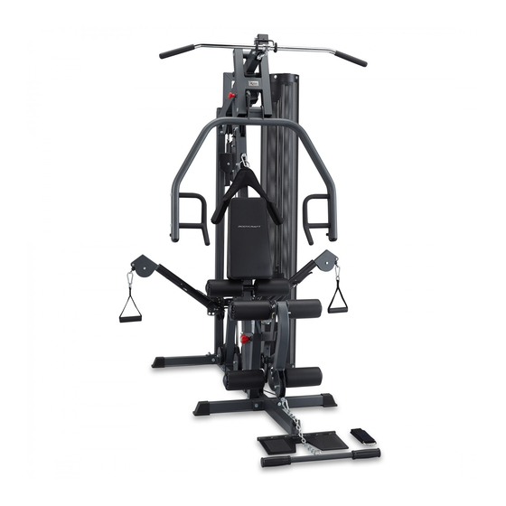
STRENGTH TRAINING SYSTEM
INSTRUCTION MANUAL
QUESTION?
As a quality home gym supplier we are committed to your complete satisfaction. If you have questions,
or find missing or damaged parts, we will guarantee your complete satisfaction through our authorized
dealer service centers or our home office customer service department. Please call your local dealer
for assistance or RSI at 800-990-5556 (9:00 AM - 5:00 PM). Our trained technicians will provide
immediate assistance to you, free of charge.
We stand behind our products. Every piece, every part of this BODYCRAFT strength training system
is guaranteed for as long as you own it. We will repair or replace anything that goes wrong.
Bodycraft is a division of Recreation Supply Inc.
P.O. BOX 181
Sunbury, OH 43074
Advertisement
Table of Contents

Subscribe to Our Youtube Channel
Related Manuals for BodyCraft XPress


Summary of Contents for BodyCraft XPress
-
Page 1: Instruction Manual
We stand behind our products. Every piece, every part of this BODYCRAFT strength training system is guaranteed for as long as you own it. We will repair or replace anything that goes wrong. -
Page 4: Table Of Contents
PARTS CHART NO. DESCRIPTION QTY. BASE FRAME REAR STABILIZER REAR UPRIGHT FRONT UPRIGHT TOP FRAME GUIDE ROD TOP GUIDE ROD RETAINER PRESS ARM SELECTOR PRESS ARM FRONT STABILIZER SEAT FRAME LEG EXTENSION ARM LOW ROW CONNECTOR FOOT PLATE FOOT PLATE ROLLER CHROME SEAT ADJUSTER SEAT BACK ADJUSTER LAT BAR HOLDER... - Page 5 PARTS CHART NO. DESCRIPTION QTY. BIG PULLEY SMALL PULLEY OF SWIVEL ARM RUBBER DONUT ADJUSTABLE STOPPER FOOT PLATE STOPPER BACK BRACKET STOPPER TOP PLATE 10 LB. PLATE SELECTOR ROD NON SLIP SNAP HOOK LOW ROW CHAIN HAND GRIP OF CABLE ARM AB CRUNCH FOAM PAD BACK PAD...
-
Page 6: Base Frame
TEP 1 ASSEMBLE MAIN FRAME To ease the assembly process, do not tighten bolts until instructed. 1. Attach Rear Stabilizer(2) to Base Frame(1) using two 3/8"X3" Bolts(88), four 3/8" Washers(101) and two Nuts(107). Attach Front Stabilizer(10) and Low Row Connector(13) to Base Frame(1) using two 1/2"X3" Bolts(85), and two Nuts(106). -
Page 7: Pres Arm
TEP 2 ASSEMBLE PRESS ARM & CABLE ARM ASSEMBLY 1. Attach Press Arm Selector(8) to Top Frame by aligning holes and inserting Pivot Axle(31). Lock into place with pre-installed set screw. 2. Attach Press Arm(9) to Press Arm Selector(8) by aligning holes and inserting Pivot Axle(31). Lock into place with pre-installed set screw. -
Page 8: Leg Extension Arm
TEP 3 ASSEMBLE SEAT FRAME AND SEAT BACK 1. Attach Seat Frame(11) to Front Upright(4) using two 3/8"X3" Bolts(88) four 3/8" Washers(101) and two Nuts(107). Attach Seat Frame(11) to Base Frame(1) using one 3/8"X4-1/2" Bolt(87), two 3/8" Washers (101) and one Nut(107). 2. - Page 9 TOP CABLE 182" (4630mm) length Assemble cables and pulleys simultaneously. Insert threaded end of Top Cable(80) into the slot in front of Top Frame(5)(Fig 1) and route over top of two pulleys mounted in Top Frame (Fig 1, 2), over left side (as if sitting on seat) pulley in Press Arm Selector (8) (Fig 3, Step 1), under pulley mounted in Front Upright, over right side pulley in Press Arm Selector (Fig 3, Step 2), then over pulley mounted in Front Upright (Fig 3, Fig 4), down to top Double Pulley Block(26)(Fig 6), up and over left side pulley on Top Frame(Fig 7), down and around top pulley...
-
Page 10: Cable Arm
AB CRUNCH CABLE 174" (4420mm) length Route the AB Crunch Cable(78) through slot and over pulley on Front Upright(Fig 1), down to the front pulley on top of Cable Arm Assembly(Fig 2), then up to lower pulley on double pulley block(26)(Fig 3), down through the rear pulley on Cable Arm Assembly (Fig 4) to pulley on Base Frame (Fig 2), then forward toward Leg Extension Arm. -
Page 11: Adjustable Pulley Block
CABLE ARM CONNECTING CABLE 185" (4710mm) length Attach pulley on base frame near weight stack as shown Fig 1 with ball end of cable toward weight stack. Route cable up to low pulley of adjustable pulley block (Fig 2), then down to pulley on Base Frame (Fig 3), up to right side pulley in Top Frame (Fig 4) and thread into the Single Pulley Block( 27)(Fig 5). - Page 12 CABLE ARM CABLE 213" (5410mm) length Attach pulley and Pulley Guide Bracket(24) to Cable Arm Assembly as shown in Fig 3 and Fig 4, Be certain that, when tightened, the Pulley Guide Brackets do not interfere with the cable movement. Route Cable Arm Cable (81) around these pulleys as shown and around pulley in the Single Pulley Block (27)(Fig 5).
Need help?
Do you have a question about the XPress and is the answer not in the manual?
Questions and answers