Table of Contents
Advertisement
Quick Links
Advertisement
Table of Contents

Subscribe to Our Youtube Channel
Related Manuals for Peak 440


Summary of Contents for Peak 440
- Page 1 Original Original FOUR POST LIFT Model: 440 440E...
-
Page 2: Table Of Contents
CONTENTS Product Features and Specifications ............1 Installation Requirement ..............2 Steps of Installation ................4 Exploded View ...................29 Test Run ..................40 Operation Instruction ................ 42 Maintenance ..................43 Trouble Shooting ................44 Lift Disposal..................44... -
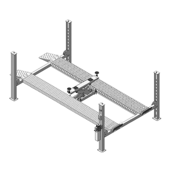
Page 3: Product Features And Specifications
Manual hydraulic power system, cable-drived. ● Strengthen and Non-skid diamond platforms. ● Adjustable platform and adjustable safety lock ladders. ● Optional Jack: With Pneumatic hydraulic pump ● Fig.1 Model: 440 440E MODEL SPECIFICATIONS Overall Width Lifting Lifting Lifting Length Overall... -
Page 4: Installation Requirement
II. INSTALLATION REQUIREMEN A. TOOLS REQUIRED Rotary Hammer Drill ( Carpenter’s Chalk Φ3/4 Hammer Screw Sets Level Bar Tape Measure ( 295-1/4” English Spanner (12") Pliers Wrench Set : Lock Wrench #... - Page 5 B. Equipment storage and installation requirements. The equipment should be stored or installed in a shady, normal temperature, ventilated and dry place. C. The equipment should be unload and transfer by forklift. × √ Fig. 3 D. SPECIFICATIONS OF CONCRETE (See Fig. 4) Specifications of concrete must be adhered to the specification as following.
-
Page 6: Steps Of Installation
III. STEPS OF INSTALLATION A. Location of installation Check and insure the installation location (concrete, layout, space size etc.) is suitable for lift installation. B. Check the parts before assembly .Received lift with hydraulic power unit (See Fig. 5) Power unit Fig. - Page 7 . Move aside the parts and check the parts according to the shipment parts list (See Fig. Fig.8 . Open the parts box and check the parts according to the parts box list (See Fig. 9) Fig. 9...
- Page 8 7. Check the Parts bag according to the parts bag list (See Fig. 10) Parts bag 1 Fig.10...
- Page 9 C. Use a carpenter’s chalk line to establish installation layout, make sure the size is right and base is flat (see Fig. 11). Note: Reserve space before and behind the installation site. Car in Direction Use a carpenter’s chalk line to establish installation layout Off-side column Power-side column...
- Page 10 D. Install cross beams (See Fig. 12) Hole towards inside Fig. 12 E. Fix the anchor bolts 1. Prepare the anchor bolts (See Fig. 13). Spring washer Washer Fig. 13 Using the prescribed rotary hammer drill, and drill all the anchor holes and install the anchor bolts, do not tighten the anchor bolts first (See Fig.
- Page 11 F. Install the safety ladders 1. Take off the pulley safety cover and unscrew the four upper nuts of the Safety Ladders, and then adjust the four lower nuts to be at the same position, then install the safety ladders (See Fig.
- Page 12 G. Put the Cross Beams at the same height (See Fig. 17). The four primary safety locks are adjusted to be locked to the safety ladders at the same time Lifting Both Cross Beams to the same height Lifting Both Cross Beams to the same height, it is recommended to about 100mm height Fig.
- Page 13 H. Install power side platform. 1. Put the power-side platform upon the cross beams by fork lift or manual, offset the cross beam to the outside till the pulleys of both platforms can set up into the cross beam (See , Install the power-side platform and screw up the bolts Fig.18) (See Fig.19).
- Page 14 I. Assemble offside platform and slider block. (see Fig.20), check the vertical of columns with Level bar, adjust with the shims if not, and then tighten the anchor bolts (See Fig. 21) check the vertical of columns with Level bar, adjust with the shims Offside platform Power-side platform 3-15...
- Page 15 (See Fig. 22) 1. Pass through the cables from the platform to the columns according to the number of the cables Fig. 22 ○ ○ ○ ○ Cable 440 Length 4915mm 14830mm 7115mm 12645mm (inc. connecting fitting) 440E Length 6405mm 17775mm...
- Page 16 2. The cable pass through the cross beam to top plate of columns and be screwed with cable nuts then install cable limit pin (See Fig. 23, Fig.24), (See Fig.25) Cable pass through between the Cable pass through top plate and big pulley and tension pulley be screwed with cable nuts.
- Page 17 3. Illustration for platform cables (See Fig. 26, Fig.27, Fig.28) cable ④ cable ② cable ④ Limit Slider cable ② cable ① cable ③ Fig.26 cable ④ cable ③ cable ④ cable ② cable ② cable ① Fig.27 Limit slider cable ④...
- Page 18 K. Install oil-water separator, manual control air valve and power unit (See Fig.29 ) Power-side column 24 25 26 27 28 30 22 Air inlet Air outlet Oil-water separator gas flow direction Oil-water separator and Fig.29 Air Solenoid Valve...
- Page 19 Item Part# Description 10420145 Oil-water separator AFR-2000 10420146 Straight fitting for air line 10209009 Cup head bolt 10420076 fitting for air line 10201034 Bleeding Plug 10420147 Straight Fitting for Air Line 10420077 Air Solenoid Valve 10420148 Washer 10420149 Cup head bolt 11420150 Cover of Air Solenoid Valve 10420045...
- Page 20 L. Install hydraulic system (See Fig.30, Fig.31, Fig.32) Note: Oil hoses and oil return pipe connected to oil cylinder must be passed above the cable and cylinder inlet port must swing upward to avoid the oil hose and oil return pipe scratched by cable Oil Hose and air line across the...
- Page 21 M. Install air-line system 8*6 1. Cut black air line on the front and rear cross beam (cut the air line at the position about 60mm from air cylinder), and then connect to T-fitting. (See Fig.33) 8*6 2. Connecting front and rear cross beam cylinders by using black air line (the actual length of air line can be cut by user) (See Fig.34) 8*6...
- Page 22 Item Part# Description 440E 85090120 T fitting for air line 10481013 Air line φ6*φ8*10000mm (Black) 10400027 Air line φ6*φ8*13100mm (Black) 10400021 Air line φ6*φ8*7400mm (Black) 10420167B Air line φ8*φ6*220mm (Black) 4. Connecting Oil-water separator and Air solenoid valve by air line (See Fig.
- Page 23 N. Install electrical system 1. Install high limit switch (See Fig. 38) Connecting 11 & 12 (NC) of limit switch to terminals 3 & 5 control box High limit swit ○ wire Fig. 38 2. Install lower alarm limit switch (See Fig.
- Page 24 3. Connecting wire of limit switch on cross beam (See Fig. 40) Coupler Adaptor ○ 1 Pull out the adaptor. Wire A/B adaptor ○ 2 Connect adaptor with coupler of wire Terminal should be tied up with the cable Optional air line through this hole Wires of limit switch on cross Circuit Diagram...
- Page 25 4. Connecting wire with control box (See Fig. 41) Note: 1) Specification for limit switch and Air solenoid valve of wire are 2*1mm , Power source and motor cables uses cable 4*2.5mm 2) Using white bobbin to wind around wire and air line. Connect wire of air solenoid valve Connect wire...
- Page 26 5. 380V Wire connection and circuit diagram 5.1 Wire connection diagram in the control box (See Fig.42) Wire Wire of Wire of Wire Wire ○ Wire Wire of power hydraulic ○ ○ high source solenoid motor limit lower solenoid switch valve limit wire...
- Page 27 5.3 380V Circuit diagram (See Fig.44) 3 Phase Fig. 44 Circuit component Item Name Code Specification Item Name Code Specification Power switch 380V AC Push button Duplex Breaker Down Triplex Push button Breaker Pass Duplex Breaker Push button Lock Single AC contactor 24V AC Motor...
- Page 28 6. 220V Wire connection and circuit diagram 6.1 Wire Connection diagram in the control box (See Fig. 45) Wire Wire of Wire of Wire Wire Wire Wire of ○ C of power hydraulic ○ ○ high ○ D of source solenoid motor limit...
- Page 29 6.3、 220V Wire connection and circuit diagram. Fig.47 Single Phase Fig. 47 Circuit component Item Name Code Specification Item Name Code Specification Power switch 220V AC Push button Duplex Breaker Down Triplex Push button Push button Breaker PASS Duplex Breaker Push button LOCK Single...
- Page 30 O. Install spring and safety cover of cross beam (See Fig. 48) Fig. 48 P. Install Drive-in ramp, Tire stop plate. (See Fig. 49, Fig.50) Install Drive-in ramp Install Tire stop plate Fig. 50 Fig.49...
-
Page 31: Exploded View
IV. EXPLODED VIEW Fig.51... - Page 32 Parts list Item Part# Description 430E 1104481002 Power-side Column 11481641 Off-side Column 10481086 Cross Beam Slider block(HK025)59*65*190 1004354001 10201140 Anchor Bolt 3/4*6-1/2 11481036 Safety Ladder L=2090 10481018 Hex Nut M33*3.5 11400001 Power-side Platform 11481067 1104483001A Pulley shaft 1104483002A 10620064 Greasing Fitting M6 10481069 Pulley washer φ115*φ76*2.5 10481021-01...
- Page 33 Item Part# Description 430E 10209010 φ10 Snap ring 10420156 Protecting ring φ24 10420045 φ6 Washer 11481016 Pin for Drive-in ramp Φ30*550 10420005 Socket fixing bolt M5*8 10481500 Parts box 11481638 Tire stop plate 10481020 Split pin φ5*60 10620065 Shim (2mm) 10201090 Shim (1mm) 10209056...
- Page 34 Item Part# Description 430E 10420095 Screw straight fitting 6*4 10420018 Self locking nut M6 10209004 Rubber ring φ8*20*3 10420153 Cup head bolt M6*20 10420016B Pipe φ40*2*1500mm 10420152 Washer φ5 10206011 Cup head bolt M5*12 1004481010 High limit switch assy.(L=1400mm) 11420204 Protective Cover 1004481007 Low limit switch assy.(L=2250mm)
- Page 35 Item Part# Description 11400003 Cross Beam 11481618 Cross Beam Cover 10209009 Cup Head Bolt M6*8 1104332001 Limit Plate 7.75*70*40 10101029 Socket Bolt M12*20 3-5A 10420026 Lock washer φ12 3-5B 10206006 Washer φ12 11481029 Pin φ16*148 10420037 Snap ring φ16 10420033 Spring 14*1.8*100 10209021 Hex Nut M10...
- Page 36 10400017 4.2 Cylinder ( ) Exploded View 51-11 Fig. 53 Item Part# Description Dust Ring Ф45*Ф53*(5~6.5) 51-1 10209078 51-2 1004356003 Y- Ring IDI φ45*φ55*8 51-3 11481053 Head Cap 51-4 1004336002 O- Ring φ120*5.3 90° 51-5 11400033 Bore Weldment 51-6 11400031 Piston Rod Φ45*1919 51-7 11400015...
- Page 37 4.3 CONTROL BOX Part No.: 10420016 Three Phase 10420281 Single Phase Fig.54 Parts for Control Box Item Part# Description QTY. Note 33-1 10420069A Cover of Control Box 33-2 10420071 Push Button 33-3 10420070 Push Button 33-4 10420072 Push Button 33-5 10420139 Screw 33-6...
- Page 38 81523049/81523050 4.4 Power Unit ( ) Exploded View 220V/50/60Hz 380/415V 50Hz Electric Electric Power Unit Power Unit Exploded View Exploded View Fig.45...
- Page 39 Parts for Electric Power Unit 220V/50/60HZ Item Part# Description 81400180 Rubber Gasket 81400250 Start Capacitor 81400200 Run Capacitor 10420148 Cup Head Bolt with Washer 81400066 Cover of Capacitor 81400363 Motor Connecting Shaft 81400369 Manifold Block 10209149 Lock Washer 81400276 Socket Iron Plug 81400259 Red Plastic Plug 85090142...
- Page 40 Part lift for 380V/415V 50Hz Electric Power Unit Item Part# Description 71150010 AMGO Power Unit name plate 81400300 Cup Head Bolt 81400363 Motor Connecting Shaft 81400369 Manifold Block 10209149 Lock Washer 81400276 Socket Iron Plug 81400259 Red Plastic Plug 85090142 Socket Bolt 81400292 Gear Pump...
- Page 41 Illustration of Hydraulic Valve for power unit (See Fig.57) Protective ring Oil return port Relief valve Release valve Throttle valve Oil Outlet Check valve Fig.57...
-
Page 42: Test Run
V. TEST RUN 1. Fill the reservoir with approximately 26L Hydraulic Oil (Note: In consideration of Power Unit’s durability,please use Hydraulic Oil 46#). Push button , the Cables will be strained. Check whether the Cables match the Pulley. Make sure the Cables are not across. 3. - Page 43 7. After finishing the above adjustment, test running the lift with load. Run the lift with Platforms in low position first, make sure the Platforms can rise and lower synchronously and the Safety Device can lock and release synchronously. And then test run the lift to the top completely.
-
Page 44: Operation Instruction
VI. OPERATION INSTRUCTIONS To lift vehicle 1. Keep clean of environment near the lift; 2. Drive vehicle to the Platform and put on the brake; 3. Turn on the power and push button UP , raise the lift to the working position; Note: make sure the vehicle is steady when the lift is raised. -
Page 45: Maintenance
VII. MAINTENANCE SCHEDULE Monthly: 1. Re-torque the anchor bolts to 150 Nm; 2. Lubricate cable with lubricant; 3. Check all cable connection, bolts and pins to insure proper mounting; 4. Make a visual inspection of all hydraulic hoses/lines for possible wear or leakage; 5. -
Page 46: Trouble Shooting
VIII. TROUBLE SHOOTING TROUBLE CAUSE REMEDY 1. Start Button does not work 1.Press start button. 2.Wiring connections are not in good 2.Repair all wiring connections condition Motor does 3. Motor burned out 3.Repair or replace motor not run 4. AC contactor burned out 4.Replace AC contactor 5. - Page 47 PEAK CORPORATION No. 3 Luomu Road,Shishan Town,Nanhai District,Foshan(528225),Guangdong,China Tel:86-757-81102815 81102805 Fax: 86-757-81102809 Email: peak@peaklift.cn http://www.peaklift.cn Manual Part No.: 72240002 72114610 Revision Date: 20223/12...
Need help?
Do you have a question about the 440 and is the answer not in the manual?
Questions and answers