Table of Contents
Advertisement
Quick Links
Advertisement
Table of Contents

Subscribe to Our Youtube Channel
Related Manuals for Kval 555


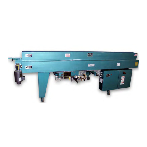
Summary of Contents for Kval 555
- Page 1 KVAL INC. INSTRUCTION MANUAL Door Sizer REV.2...
- Page 3 This document, the information in this document, and all rights there to are the sole and exclusive property of Kval, are intended for use by customers and employees of Kval, and are not to be copied, used, or disclosed to anyone, in whole or in part, without the express written permission of Kval.
- Page 5 No._____________________________________________ DATE OF PURCHASED___________________________________ This manual is designed with safety in mind. We at KVAL want to begin FAST and SAFE production as soon as possible. It is very important that all OPERATORS and MAINTENANCE personal read this manual thoroughly. We have included important safety information that will help prevent serious injury;...
-
Page 7: Customer Service Information
Customer Service Information KVAL is happy to help its customer make the most of their investment, and help solve any problems that may occur. When you call, please have the electrical print, air print number, and the serial number of the machine ready, so that we are able to accommodate your needs efficiently. - Page 8 2. Including Packing Slip # 3. Include your RMA # on the outside of the package so our shipping receiver will see it. Kval tries hard to satisfy its Customers, if you have any questions concerning merchandise purchased through KVAL, please call.
- Page 9 Getting Started Your new KVAL Machine arrives at your plant crated, banded, taped and has painted set collars on all shafts; keeping all of the precision moving parts secure during shipping. 1. Move the machine as close to the area it will be stationed before removing the crate to protect against damaging the machine with the forklift.
- Page 10 Safety First Danger This section contains important safety information. Failure to follow these safety guidelines may subject the operator to physical hazards that may result in serious bodily arm, or death.
- Page 11 Responsibility It is the responsibility of each employee to maintain safe working conditions in his or her area. Failure to understand and correctly follow this procedure is direct violation of safety rules and regulations. Violations of this policy can lead to severe injury. PROCEDURE To lockout or tag out a piece of equipment, the following steps must be taken: 1.
- Page 12 7. Before removing the lock and tag, the person who attached them shall inspect the equipment to ensure that the machine will not be put in an unsafe condition when re- energized. 8. The lock and tag can now be removed (only by the person who place them), and the machine can be re-energized.
- Page 13 Lock out and Tag Out Procedure 1. P..PROCESS SHUTDOWN 2. R..RECOGNIZE ENERGY TYPE 3. O..OFF - SHUT OFF ISOLATING DEVICES 4. P..PLACE LOCK AND TAG 5. E..ENERGY RELEASE STORED ENERGY (0 ENERGY STATE) 6. R..RECHECK CONTROLS AND RETURN TO PROPER SETTING ENERGY TYPES Recognize the Types of Energy to Shut Down 1.
- Page 14 LOCK RULES 1. Use an appropriate “Lock-Out Device”, such as Lock Tongs, or a Lock Tag. Each person must attach his or her own lock to the Lock-Out Device. 2. Identify Locks Each lock will be identified by a number or a name. A lock without a tag is not good enough. Additional information that identifies the person / persons doing the work must be on the tag.
- Page 15 P-R-O-P-E-R HYDRAULIC AND/OR PNEUMATIC LOCK-OUT P Process Shut Down Shut down process using recommended procedures. R Recognize Energy Type Recognize all sources of energy – the electric that powers the pumps or compressors, and the air or hydraulic valves themselves. O Off! -Shut off all Power Controls Shut off each energy type.
- Page 16 P-R-O-P-E-R MECHANICAL ENERGY LOCK-OUT Mechanical Energy may be released at the point of operation, or where two or more points of operation come together. This is where you might get caught. In most cases blocking mechanical energy is done in addition to shutting off the primary source, such as electrical, hydraulic and pneumatic.
-
Page 17: Zero Energy Start Up
ZERO ENERGY START UP Zero Energy State to Start-up to Operating State Starting the equipment is just as important as Lock-Out/Tag-Out in terms of safety. Start-up • Inspection • Clean up • Replace guards • Check controls • Remove locks •... -
Page 18: Safety Guidelines
Safety Guidelines ELECTRICAL Electrical circuitry on this machine is protected by an approved lockable disconnect circuit. In addition to this equipment, you must install an approved disconnect for the electrical power supplying this machine. COMPRESSED AIR The compressed air system connected to this machine should have a three-way air valve for shut-off and pressure relief. -
Page 19: Emergency Stop
When pressing the “Emergency Stop”, the cutter, easers, sanders, feed wheels stop, and the feed arms rise. Start Button The “Start” foot pedal begins the 555 cycle of operation, if there is a door inserted into the 555 far enough to activate the first limit switch. Press once to Start. - Page 20 6. Re-tighten the two fastening bolts, and the lock nut on the Jackscrew. PLUG IN THE ROUTERS 8. To check the amount eased, run a door into the 555 and ease about 3” from the top of the door, then press the “Emergency Stop” button.
- Page 21 Door Thickness The Easers allow both 1-3/8” and 1-3/4” doors to pass through the 555 machining a 45-degree bevel on both edges of the door. Carefully adjust the Easers so that the 1-3/8” door barely opens them. If the 1-3/8” door opens the Easers, too much a 1-3/4”...
-
Page 22: Changing The Sanding Belt
The cutter plate pivots on one 1/2” bolt when the two bolts supporting the cutter plate are loosened. Once the two bolts are loose turn the Jackscrew in or out until the 555 bevel is correct. Make a test cut. - Page 23 2. Turn the Index switch to the “ ” position. 3. Slide the carriage to the measurement that you want by reading the Tape Indicator on the left end of the 555. 4. Turn the Clamp switch to the “ ” position.
- Page 24 With Index Clamp engaged, turn Fine Adjustment Wheel to move carriage in the direction you want. When the Tape Indicator on the left end of the 555 frame shows the measurement, you want turn the Allen wrench locking the adjustment shaft in place.
- Page 25 Maintenance Schedule Maintenance Schedule KVAL recommends the following maintenance schedule to ensure that the machine operates properly. Refer to this section for steps to perform maintenance. Daily, Monthly, Six Month Maintenance Daily Preventive Maintenance Operation Description Clean Blow off dust from the entire machine.Wipe down the outside of the machine with a clean dry cloth.
- Page 26 Maintenance Schedule Lubrication Schedule KVAL recommends the following lubrication schedule to ensure that the machine operates prop- erly. Recommended Lubrication Schedule TABLE 3-1. Type of Assembly Recommended Schedule Recommended Lubrication Type Linear Bearing Pillow Block Bearing Every 250 Hours of Machine Operation...
-
Page 28: Lubrication Requirements
PD2) bearings must be re-lubricated once every 60 days. Approved Lubrication Products Chevron AW Hydraulic Oil 32 – or KVAL P/N SYSLUBG or G-C lubricants light AW R&O or Mobile DTE 24 or Shell Tellus32 or Gulf Harmony 32. Lubricator Adjustments Using knob on the top of the lubricator, adjust until one drop per every other cycle is used (as observed through sight glass.) Turn flow all the way open then reduce flow... - Page 29 Mist Oil Lubrication Spindle housing mist oilers require syslube lubricant, available through KVAL. Optimum flow is 3 to 5 drops per minute @ 5-10 psi. NOTE: These oils cannot be interchanged. Priming the Lubricator New and used machinery run out of oil from time to time. It is a good practice to check your machine lubricator to insure that it is putting the proper dose of oil in the air lines.
-
Page 33: Limit Switches
TROUBLE SHOOTING LIMIT SWITCHES If a machine suddenly stops in mid cycle check the limit switches, a worn limit switch arm or a misadjusted limit switch is more than likely the cause. Depending on the model of limit switch you receive the amount of “pre-travel”... -
Page 34: Photo Eyes
PHOTO EYES The sending and receiving eyes “talk” to each other when the beam between the two is broken by either a door a moving part on the machine such as the thru beams, these beams may either stop operation or initiate operation depending on their location and function. PHOTO EYES The sending and receiving units are in one unit, these operate in the same manner as the ones described previously. - Page 35 GENERAL AIR CIRCUITRY TROUBLE SHOOTING IF A CYLINDER IS NOT FUNCTIONING CORRECTLY HERE ARE A COUPLE OF ITEMS TO CHECK: Most cylinders have an extend and retract port. To adjust the extend motion of a cylinder you must adjust the flow control on the retract port; this regulates the air flow exhausting from the cylinder and the opposite is true for the retract motion.
- Page 36 It maybe is necessary to purchase a rebuild kit or a new cylinder. 6. If the valve is not receiving an electrical signal, see “Electrical Trouble Shooting” instruction. It might be necessary to call in a specialist or check with KVAL customer service at 1-800-553-5825 If an Air Leak is coming from an exhaust port on the solenoid air bank: Check the solenoid for the manual override.
-
Page 37: Basic Electrical Trouble Shooting
BASIC ELECTRICAL TROUBLE SHOOTING THE FOLLOWING SHOULD ONLY BE ATTEMPTED BY TRAINED ELECTRICAL PERSONNEL. The electrical component systems are designed to expedite the troubleshooting process and minimize “down time”. In general, component systems have the input or feed functions at the top. Output or load functions are positioned at the bottom. Most two voltage electrical panels are designed with the LOW VOLTAGES on the LEFT, and the HIGH VOLTAGES on the RIGHT. - Page 38 DANGER The following checks will require the electrical panel to be energized these trouble shooting checks MUST BE PERFORMED BY A QUALIFIED ELECTRICAL TECHNICIAN. 1. Remove lock and tag outs on the main power sources 2. Manually close disconnect switches and energize the control circuit or transformer with its respective switch.
- Page 40 Contacting KVAL Customer Service Phone and Fax: Mailing address: In the U.S and Canada, call (800) 553-5825 or fax Customer Support Department (707) 762-0485 Kval Incorporated Outside the U.S. and Canada, call (707) 762-7367 825 Petaluma Boulevard South or fax (707) 762-0485 Petaluma, CA 94952 Email: service@kvalinc.com...
Need help?
Do you have a question about the 555 and is the answer not in the manual?
Questions and answers