Table of Contents
Advertisement
Quick Links
Advertisement
Table of Contents

Subscribe to Our Youtube Channel
Related Manuals for Kval 558


Summary of Contents for Kval 558
- Page 1 Operation Manual Published: 1/14/19 Innovation, Quality & Honesty 558 Door Sizer...
- Page 2 This document contains confidential and trade secret information, which is proprietary to Kval, Inc. (“Kval”), and is protected by laws pertaining to such materials. This doc- ument, the information in this document, and all rights thereto are the sole and exclu-...
- Page 3 KVAL 558 Operations Manual Your Feedback is Welcome: To help us design products that make your job easier and your business more successful, we'd like to gain your perspective about your user experience with our product - that is, the manual, the machinery, the software, etc.
- Page 4 KVAL 558 Operations Manual...
-
Page 5: Table Of Contents
Table of Contents Introduction to the 558 Door Sizer Chapter 1 Chapter 1 at a Glance.............. 1-1 Overview of the 558 Door Sizer..........1-2 About this Manual .................1-2 Safety First!................1-3 Safety Sheet Sign-Off Sheet..............1-3 Safety Terminology of Labels..............1-3 Safety Guidelines..................1-3 Lockout Tagout Procedure..............1-7... - Page 6 Description of the Preset Setup Screen..........2-30 Description of the Diagnostic Screen..........2-30 System IT Administration Chapter 3 System IT Administration............3-2 About the 558 Computer...............3-2 Connections on the PLC...............3-2 Backing up the Computer ..............3-3 About Remote Connection to KVAL Service.........3-3 558 Door Cutter...
-
Page 7: Chapter 1 At A Glance
Chapter 1 at a Glance CHAPTER 1 Introduction to the 558 Door Sizer Chapter 1 at a Glance This chapter provides an overview of the KVAL 558 Door Sizer and important safety information to follow Overview of the 558 Door Sizer ..............1-2 About this Manual .................. -
Page 8: Overview Of The 558 Door Sizer
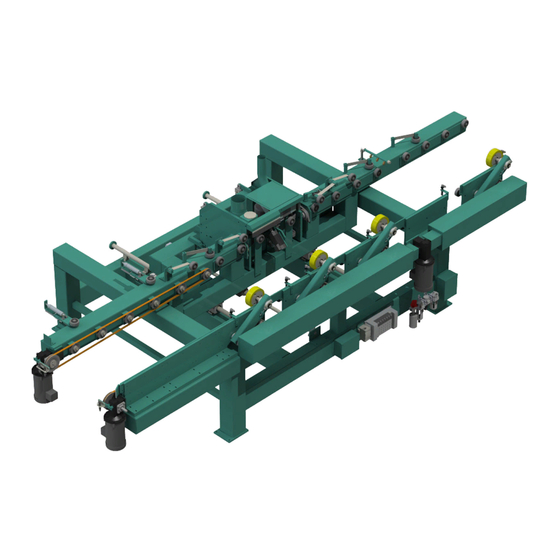
Overview of the 558 Door Sizer Overview of the 558 Door Sizer The KVAL 558 Door Sizer is designed to resize doors to the correct width and bevel. This machine features a 5” cutter head with 50 mm replaceable inserts. The cutter head is spindle driven with a 5 HP motor and adjusts from a 0 degree to 3 degree bevel. -
Page 9: Safety First
See “Safety Sign-Off Sheet” on page 1-17. Safety Terminology of Labels In addition to the nameplate, KVAL machines may have other warning labels or decals that pro- vide safety information to operators. Safety labels should be clearly visible to the operator and must be replaced if missing, damaged, or illegible. - Page 10 Before performing any mainte- nance or repairs on this machine turn off the main air disconnect. Lockout and tagout this connection. See “Lockout Tagout Procedure” on page 1-7. KVAL 558 Operation Manual...
- Page 11 Prior to performing any maintenance, repairs, cleaning or when clearing jammed debris, you must disconnect, tag out, or lock out the elec- trical and air pressure systems. This should be done in accordance with applicable state and/ or federal code requirements. KVAL 558 Operation Manual...
- Page 12 Safety First! Compliance with Codes and Regulations KVAL advises that you request an on-site state safety review of your installation of this machine. This is to ensure conformance to any additional specific safety and health regula- tions which apply in your geographic area.
-
Page 13: Lockout Tagout Procedure
OFF position. Then pull out the red tab and place a padlock through the hole. Place your tag on the padlock, as per the tagout guidelines below. KVAL 558 Operation Manual... - Page 14 • If more than one person is working on the machine, then each additional person places a lock and tag on each disconnect. • Only each operator may remove their own lock and tag. KVAL 558 Operation Manual...
-
Page 15: Follow The P-R-O-P-E-R Lockout Rule Of Thumb
O..OFF! Shut off all power sources and isolating devices P..Place lock and tag E..ENERGY: Release stored energy to a zero-energy state R ..Recheck controls and test to ensure they are in the “OFF” state KVAL 558 Operation Manual... -
Page 16: Zero-Energy To Start-Up
Replace Guards Replace all equipment guards. If part of equipment cannot be properly adjusted after start-up with guard on, contact the KVAL Service team. See “Getting Help from KVAL” on page 1-12. Check Controls Confirm that all switches are in the “OFF”... - Page 17 P-E-R lockout/tagout procedures, and that those around you do also. Close the Cage Gate Verify all cage gates are securely closed. Ensure all safety protocols are in effect. LOCKOUT YOUR LIFE MAY TAGOUT DEPEND ON IT KVAL 558 Operation Manual 1-11...
-
Page 18: Getting Help From Kval
Chapter 3 “System IT Administration” on page 4-1, for more information. Product Return Procedure If you’ve contacted Kval for help and it is determined that a return is necessary, use the procedure below to return the machine or part. - Page 19 • With what equipment is the unit interfaced? • What was the application? • What was the system environment (temperature, spacing, contaminants, etc.)? Call Kval customer support for a Return Material Authorization (RMA). When you call: • Have the packing slip or invoice numbers available.
-
Page 20: How To Download The Service Application
Download Application To download the application, go the KVAL website ( http:// www.kvalinc.com At the KVAL website, select the tab. Follow the instruc- Support tions on the Support web page. Click the Download button to download the application that... - Page 21 Session code: An internal number to track this machine. It is auto filled. Your Name Field: Enter your name. The KVAL tech- nician will use this field to identify this machine. Description: Enter machine Serial number and issue.
- Page 22 How to Download the Service Application Page Intentionally Left Blank KVAL 558 Operation Manual 1-16...
-
Page 23: Safety Sign-Off Sheet
Name (print):__________________Signature: __________________ Date:____/____/___ Note: It is recommended you make a copy of this sheet for new operators. If a copy is needed, you may download a PDF at the KVAL website ( http://www.kvalinc.com You may also contact our Service Department at (800) 553-5825 or email at ser- vice@kvalinc.com. - Page 24 Safety Sign-Off Sheet KVAL 558 Operation Manual 1-18...
-
Page 25: Chapter 2 Operation Of The 558
This chapter describes components, assemblies, and the user interface of the KVAL 558. The con- tent is geared to help operators understand the basic operation of the 558. Included are instruc- tions to calibrate the machine and run a door. -
Page 26: Operator's Tour
Operator’s Tour Operator’s Tour This section identifies the basic components of the KVAL 558 Door Sizer system. Sensors located at the In-Feed, the In-Feed Push Over Cylinder Out-Feed and down the length of the 558 Width Adjust Fence Servo Width... -
Page 27: Sensors
Operator’s Tour Sensors Optical (eye) sensors are located along the door path of the 558 to keep track of the door during the cut. When blocked, the sensors send signals to the computer to identify location of the door or process. - Page 28 Before Wheel 2 I-0015 Brings Wheel # 2 down to secure door when blocked, wheel goes up when clear. Before Wheel 3 I-0016 Brings Wheel # 3 down to secure door when blocked, wheel goes up when clear. KVAL 558 Operation Manual...
- Page 29 Operator’s Tour Out-Feed Eye The Out-Feed eye is located after the last wheel on the operator side of the 558. Door Sense Eye After the Out-Feed Wheel (I-0017) Location of Out-Feed Eye FIGURE 2-6. Home Sensor, Width Limit Sensors The width adjust is determined by ferrous proximity sensors The home eye sets the zero reference of the calibration.
- Page 30 If the zero or three degree bolt needs to be adjusted, the sensor will need to be Note: adjusted to correspond with the change. Refer to the “KVAL 558 Service Man- ual” for information on adjusting the Zero and Three Degree Bolt.
-
Page 31: Valve Bank
Valve Bank The valve bank consists of seven solenoid valves that control air flow to drive assemblies on the 558. The valves are attached to a manifold base. The terminal block supplies interfaces with digi- tal-signals and supplies power. When the Drive Wheel valves are activated, the top red lights will turn-on. -
Page 32: Cutter, Easer, And Sander
Cutter Head Sanding Belt Easer Router Bit Easer Motor 1 of 2 Rear View Sander Motor Easer Motor 2 of 2 Direction of Motor Rotation Cutter Motor Front and Rear View of Cutting Assembly FIGURE 2-10. KVAL 558 Operation Manual... -
Page 33: Identification Of Electrical Panel Parts
Over- (3 Pole Contactor) load Circuit Control Transformer Fixed Fence Drive Wheels VFD Sander Motor VFD Cutter Motor Top Easer Motor VFD Bottom Easer Motor VFD Assembly Description in the Electrical Panel FIGURE 2-11. KVAL 558 Operation Manual... -
Page 34: Description Of The Six Light Panel
Operator’s Tour Description of the Six Light Panel The six lights on this panel indicate the status of the 558 system. Refer to the “KVAL 558 Service Manual” for information on using the panel for Note: troubleshooting. The Sequence that the lights activate is as follows:... -
Page 35: Snapshot Of Door Cutting Process
Snapshot of Door Cutting Process Snapshot of Door Cutting Process This section describes the steps run a Door through the KVAL 558. Turn On Control Transformer Home Machine Sizing Feed -Thru Press “Feed-Thru” so it Press”Auto Feed” so it Sizing or... -
Page 36: Basic Operation
Tip: The lights on the six light panel should all illuminate on a successful start-up. Wait for the computer to boot up and the 558 Start-Up screen to display. Remove any door in the feed system. Make sure area is clear. -
Page 37: About Homing Of The 558
558 measures its movement and cutting process. If power is lost or the 558 is re-set, the homing routine must be performed again to reset the zero reference The routine is as follows:... -
Page 38: How To Power Down The 558
Basic Operation How to Power Down the 558 Turn off the Computer by pressing the Step 1 button. Located Shut Down System lower right hand corner of the Main Screen Step 2 After the computer has gone blank, on the front panel, push the... -
Page 39: If Safety Gate Is Opened During Run
If Safety Gate is Opened During Run At the back of the 558 is a safety gate on the security fence. If the gate is opened, the effect is the same as pushing the stop button or pushing the touch screen system off button. To recover, secure gate and restart machine. -
Page 40: Description Of User Interface Screens
This section describes the user interface screens. The user interfaces allow the operator to control the door cutting process, auto-run and manually run the door, store door profiles, and use diagnos- tics to help troubleshoot the 558. The user interfaces include the following: • Main Screen •... - Page 41 Cut Offsets Setup played as active buttons on the main screen. See “Offset Setup” on page 2-32. At the Main Screen, select the desired offset. All Presets will be updated with the selected offset Process the door. KVAL 558 Operation Manual 2-17...
- Page 42 • Feed Through Enabled: Uses the Feed-through Offset data entered in the Setup Screen. (See “Feed-thru Offset:” on page 2- 30.) The door will be fed through the 558 at this width without be machined. • Feed Through Disabled: Uses the preset setting and width...
- Page 43 Click the 1 3/8 box if door thickness is 1 3/8” thick. Click the 1 3/4 box if door thickness is 1 3/4” thick. 0 Deg and 3 Deg 0̊ Deg / 3 Deg : Click to toggle between 3 degree and 0 degree parameters. KVAL 558 Operation Manual 2-19...
- Page 44 The home sequence must be performed every time the machines is turned on or reset. (See “About Homing of the 558” on page 2-13.) KVAL 558 Operation Manual...
- Page 45 • Top Line: indicates the machine status. • Feed: indicates the condition of the feed circuit. • Head: indicates if the Cutter is ON or OFF KVAL 558 Operation Manual 2-21...
- Page 46 “Auto Width Eye:” on page 2-28.) Preset Selections This selection of buttons allows a quick way to load the preset widths of a saved door. The preset values are created in the Preset Menu. (See “” on page 2-30.) KVAL 558 Operation Manual 2-22...
-
Page 47: Manual Screen
Description of User Interface Screens Manual Screen The Manual Button opens the Manual Screen. The Manual Screen interface allows the operator to manually control machine speed, direction and width servo position. KVAL 558 Operation Manual 2-23... - Page 48 Setup Mode Enabled: This will open the width adjust carriage a half inch. The door feeds through the 558 normally, except all cutting motors turn off and no cutting, easer routing, and sanding is per- formed. Enabled mode is normally used to check the Note: system.
- Page 49 Feed Wheels Feed Wheels Up/Feed Wheels Down: This button toggles the Feed Wheels up and down. Auto Width Mode: Refer to “ Auto Width Mode:” on page 2-18 for Auto Width description. KVAL 558 Operation Manual 2-25...
-
Page 50: Description Of The Setup Screen
See “Feed Through Mode:” on page 2-18. Feed Through Mode: See “Feed Through Mode:” on page 2-18. Exit Application: Click the button to exit out of the 558 program and go ® back to the Windows CE desktop. Description of the Setup Screen From the Setup Screen, the operator can make general adjustments and calibration adjustments. - Page 51 Description of User Interface Screens KVAL 558 Operation Manual 2-27...
- Page 52 Once this is done, click Main button and select the preset width and re-run the door. Repeat steps 3-5 until Measure Width is the same number as the door. After calibration is completed, click Com- to store data. bine with Base KVAL 558 Operation Manual 2-28...
- Page 53 After calibration is completed, click Com- to store data. bine with Base 3 Degree Calibration: Follow the same steps as in the 0 degree cali- bration except run a 3 degree door. KVAL 558 Operation Manual 2-29...
- Page 54 Remodel Door Offset: Click the white box under the title to enter the Remodel door offset number. This offset combines with all the presets when the Remodel Door Button is enabled. See “Remodel Mode:” on page 2-20. KVAL 558 Operation Manual 2-30...
-
Page 55: Description Of The Preset Setup Screen
Interfaces starting in 2019 includes a Input Window at the bottom of the screen. Select Preset Title Enter desired Label. Select Preset Width Enter desired width value Select the Save Preset Button. The Preset button will be pop- ulated on the grid. KVAL 558 Operation Manual 2-31... - Page 56 The offset value will be reflected on the buttons located on the Main Screen Follow steps 1 through 4 for each offset that needs to be updated. KVAL 558 Operation Manual 2-32...
-
Page 57: Description Of The Diagnostic Screen
Description of the Diagnostic Screen The Diagnostic Screen displays the all the tasks the 558 performs. This screen will help with trou- ble shooting. The top line will have the most current routine that is running. Read the error and if the problem is not resolved, call KVAL Inc. - Page 58 Description of User Interface Screens KVAL 558 Operation Manual 2-34...
-
Page 59: Chapter 3 System It Administration
CHAPTER 3 System IT Administration This chapter describes the KVAL 558 controller. The controller is an on board computer that sup- plies the user interface and controls the operation of the machine. With the controller, KVAL can remotely help troubleshoot your machine. -
Page 60: About The 558 Computer
Connection to the intranet is achieved by interfacing with the 558 control- ler. The location of the intranet connection is identified in the figure below (RJ45 to intranet.) About the 558 Computer ®... -
Page 61: Backing Up The Computer
About Remote Connection to KVAL Service Remote access is a powerful tool to help fix issues that occur with the 558 machine. With the remote access, our KVAL service technician is able to observe your user screen in real time, read ®... - Page 62 System IT Administration KVAL 558 Operation Manual...
- Page 63 2-29 infeed time software button description location internet access cutter motor location location of connection remote connection KVAL 558 Operation Manual...
- Page 64 2-18 2-20 width button reset machine software button description 1-12 manual part number return material authorization (RMA) 1-12 manual screen returning the product to Kval 2-25 auto feed mode KVAL 558 Operation Manual...
- Page 65 2-10 start light description 2-10 stop light description tagout procedure 2-18 thickness software button description three and zero degree sensors description, location three degree calibration 2-28 description 2-28 three degree calibration using setup screen KVAL 558 Operation Manual...
- Page 66 Notes:...
- Page 67 Notes:...
- Page 68 Contacting KVAL Customer Service Phone and Fax: Mailing address: In the U.S and Canada, call (800) 553-5825 or fax Customer Support Department (707) 762-0485 Kval Incorporated Outside the U.S. and Canada, call (707) 762-7367 825 Petaluma Boulevard South or fax (707) 762-0485 Petaluma, CA 94952 Email: service@kvalinc.com...
Need help?
Do you have a question about the 558 and is the answer not in the manual?
Questions and answers