Kval 990-H Operation Manual
Pre-hanging door system
Hide thumbs
Also See for 990-H:
- Service manual (66 pages) ,
- Service manual (104 pages) ,
- Operation manual (80 pages)

Subscribe to Our Youtube Channel
Related Manuals for Kval 990-H


Summary of Contents for Kval 990-H
- Page 1 Operation Manual Published: 10/24/18 Innovation, Quality & Honesty 990-H Pre-Hanging Door System...
- Page 2 Proprietary Notice This Manual is confidential and contains proprietary information and intellectual property of KVAL Inc., and is to be used solely by Customer as an operating manual for KVAL Inc. machines. Neither this Manual nor any of the information contained herein may be reproduced or disclosed under any circumstances without the express written permission of KVAL Inc.
- Page 3 KVAL 990-H Operation Manual Your Feedback is Welcome: To help us design products that make your job easier and your business more successful, we'd like to gain your perspective about your user experience with our product - that is, the manual, the machinery, the software, etc.
- Page 4 KVAL 990-H Operation Manual...
-
Page 5: Table Of Contents
Table of Contents Introduction to the 990-H Chapter 1 Chapter 1 at a Glance.............. 1-1 Overview of the 990-H Door Hanging System ......1-2 Operation ....................1-2 Features....................1-2 Options and Specials Available ............1-4 About this Manual .................1-5 Safety First!................1-6 Safety Sheet Sign-Off Sheet..............1-6 Safety Terminology of Labels..............1-6... - Page 6 Electrical Panel Option: Servo Box 2..........2-20 Description of the Six Light Panel ........... 2-21 Machine Start Summary ............2-22 Powering Operations for the 990-H ......... 2-25 How to Power Up the 990-H ...............2-25 Home the 990-H .................2-26 How to Power Down the 990-H ............2-26 Safety Controls ................
- Page 7 Table of Contents About the Pre-Drill Screen ............2-49 Entering Pre-Drill Pattern Data ............2-49 Example of Data Input ................2-50 Diagnostic Screen..............2-51 Status of I/O and E-Stops Screen..........2-52 KVAL 990-H Operation Manual...
- Page 8 Table of Contents 990-H...
-
Page 9: Chapter 1 At A Glance
Chapter 1 at a Glance Introduction to the 990-H CHAPTER 1 This chapter provides an overview of the KVAL 990-H Door Hanging System and important safety information to follow when operating the machine. Chapter 1 at a Glance Section Name... -
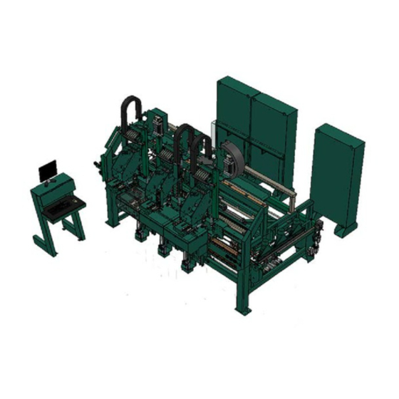
Page 10: Overview Of The 990-H Door Hanging System
Overview of the 990-H Door Hanging System Overview of the 990-H Door Hanging System The Kval Model 990-H will rout a door and jamb for two or three hinges, drill pilot holes for the hinge screws, rout and bore for the lock and apply hinges. - Page 11 Overview of the 990-H Door Hanging System Face bore; side drill and bolt plate router will be capable of shifting up to 300mm (11.811) off of center line of length of door in either direction. Total movement of 600mm. (23.622) Face bore drills will accommodate a three stage drill bit both top and bottom for drilling differ- ent diameter holes.
-
Page 12: Options And Specials Available
410mm in width, but without lock pro- cessing (Option includes complete secondary feed fence attached to the lock section of the 990-H that will nest under doors when not in use) Opt P... -
Page 13: About This Manual
Overview of the 990-H Door Hanging System Option Title Description Corner Square Feature Adds automatic corner squaring to the hinge rout- ing sequence, and fastening of square hinges. Price includes replacing x,y,z motion air cylinders on each of the hinge router head with ball screws and AC servo motor (9 total), as well as corner square chisel assemblies. -
Page 14: Safety First
See “Safety Sign-Off Sheet” on page 1-20. Safety Terminology of Labels In addition to the nameplate, KVAL machines may have other warning labels or decals that pro- vide safety information to operators. Safety labels should be clearly visible to the operator and must be replaced if missing, damaged, or illegible. - Page 15 Before performing any mainte- nance or repairs on this machine turn off the main air disconnect. Lockout and tagout this connection. See “Lockout Tagout Procedure” on page 1-11. KVAL 990-H Operation Manual...
- Page 16 This should be done in accordance with applicable state and/or federal code requirements. Laser Warnings On some machines, laser indicators are used to set boundaries. Follow the manufacturers safety precautions. KVAL 990-H Operation Manual...
- Page 17 Safety First! Compliance with Codes and Regulations KVAL advises that you request an on-site state safety review of your installation of this machine. This is to ensure conformance to any additional specific safety and health regula- tions which apply in your geographic area.
-
Page 18: Lockout-Tagout Guidelines
O..OFF! Shut off all power sources and isolating devices P..Place lock and tag E..ENERGY: Release stored energy to a zero-energy state R ..Recheck controls and test to ensure they are in the “OFF” state KVAL 990-H Operation Manual 1-10... -
Page 19: Lockout Tagout Procedure
Turn Switch to the Lock and Tag out Insert Lock into hole. OFF position Note: When multiple people are working on the machine, each person needs to have a lock on the handle in the extra holes provided. KVAL 990-H Operation Manual 1-11... -
Page 20: Lockout Tagout Air Supply
The lock and tag can now be removed (only by the person(s) who placed them), and the machine can be re-energized. The tags must be destroyed and the locks and keys returned to the lockout center. KVAL 990-H Operation Manual 1-12... -
Page 21: Zero-Energy To Start-Up
Replace Guards Replace all equipment guards. If part of equipment cannot be properly adjusted after start-up with guard on, contact the KVAL Service team. See “Getting Help from KVAL” on page 1-15. Check Controls Confirm that all switches are in the “OFF”... - Page 22 Be sure to follow the P-R-O- P-E-R lockout/tagout procedures, and that those around you do also. Close the Cage Gate Verify all cage gates are securely closed. Ensure all safety protocols are in effect. KVAL 990-H Operation Manual 1-14...
-
Page 23: Getting Help From Kval
Ask about this procedure when calling are service team Product Return Procedure If you’ve contacted Kval for help and it is determined that a return is necessary, use the procedure below to return the machine or part. - Page 24 • With what equipment is the unit interfaced? • What was the application? • What was the system environment (temperature, spacing, contaminants, etc.)? Call Kval customer support for a Return Material Authorization (RMA). When you call: • Have the packing slip or invoice numbers available.
-
Page 25: How To Download The Service Application
Download Application To download the application, go the KVAL website ( http:// www.kvalinc.com At the KVAL website, select the tab. Follow the instruc- Support tions on the Support web page. Click the Download button to download the application that... - Page 26 Session code: An internal number to track this machine. It is auto filled. Your Name Field: Enter your name. The KVAL tech- nician will use this field to identify this machine. Description: Enter machine Serial number and issue.
- Page 27 How to Download the Service Application Page Intentionally Left Blank KVAL 990-H Operation Manual 1-19...
-
Page 28: Safety Sign-Off Sheet
Note: It is recommended you make a copy of this sheet for new operators. If a copy is needed, you may download a PDF at the KVAL website (http://www.kvalinc.com). You may also contact our Ser- vice Department at (800) 553-5825 or email at service@kvalinc.com. - Page 29 Safety Sign-Off Sheet KVAL 990-H Operation Manual 1-21...
- Page 30 Operation of the 990-H CHAPTER 2 This chapter describes components, assemblies, and the user interface of the KVAL 990-H Door Hanging System. The content is geared to help operators understand the basic operation of the machine. Included are instructions to calibrate the machine and run a door.
-
Page 31: The 990-H Process Summary
The 990-H Process Summary The 990-H machines hinge pockets on both a door and a jamb and then attaches hinges to them. While the hinge process takes place a door lock and face plate is drilled. Feeding the door to the 990-H, is an ON-2012 configured as a feeder. -
Page 32: Machine Components
There are two electrical boxes, located near the back section of the machine Operator’s Station The operator’s station houses the 990-H touchscreen and other operational control switches. Note: On some options the touchscreen includes operation or other machines in the line, such as a feeder and stacker. -
Page 33: Top View Of Machine
Top View of Machine Top View of Machine This section takes you on a tour of the 990-H Pre-Hanging Door machine Operator’s Station In-Feed from Feeder Electrical Panel # 1 Option: Located On Hydraulic Extend Arm ON System X3 Machine... -
Page 34: About The Operator Station And Front Section Controls
Machine Machine Process Store Program To allow the operator Emergency Stop to make changes to Stops machine in an parameters, turn the emergency situation. to the On posi- Up Lock tion Operator Station FIGURE 2- 3. KVAL 990-H Operation Manual... -
Page 35: About The Foot Pedal And Control Box
Jamb Clamp Pedal:The jamb clamp pedal activates the jamb clamps to clamp the jamb in place. or to unclamp a jamb. Press once to clamp, press again to unclamp. See “Powering Operations for the 990-H” on page 2-25. Door Clamp / Un-Clamp Jamb Clamp / Un-Clamp... -
Page 36: Hinges Loaded Button (Status Light)
Hinge Loaded: Press after the “Start Sequence” button has been pressed and after the Six-Shooter heads have begun to move into hinge application position. This button informs the Six-Shooters that the hinges are loaded and ready to be applied KVAL 990-H Operation Manual... -
Page 37: About The In-Feed Section
Six Shooters: Supplies pressurized fluid for operation of the six shooters In Feed: Gate Auto Adjusts to in-fed door. Clamps and sends door through machine for pro- cessing Key Assemblies on the In-Feed Section FIGURE 2- 4. KVAL 990-H Operation Manual... -
Page 38: About The Front Section
Hinge Head (X3): Loca- Operator Station: tion of Routers.Predrills “About the Operator Sta- and Chisels for hinge tion and Front Section side of door. Controls” on page 2-5 Key Assemblies on the Front Section FIGURE 2- 5. KVAL 990-H Operation Manual... -
Page 39: About The Hinge Heads
See “Connections to Servo Drives” on page 6-30 . This section supplies more information about the servo drives. Key Assemblies on Heads FIGURE 2- 6. KVAL 990-H Operation Manual 2-10... -
Page 40: About The Six Shooter System
Any adjustment may cause timing issues with the operation of the Six Shooter. If you think problems are being caused by the cylinders, please contact the KVAL Service Department for direction. Important: Do not mix screw types in the Hopper. Different sizes, pitches can cause uneven application of the hinge. - Page 41 Hopper Hopper Cylin- to organize the screws and deliver them to the ders Screw Tracking Plate monitors the quantity of screws delivered to the to the Gate Assembly Screw Tracking Plate Assembly. KVAL 990-H Operation Manual 2-12...
- Page 42 ) moves upward to drain the rest of the screws out of the hopper this will Assembly cycle one more time to clear the screws from the slides. Press the button on the Six Shooter panel located mid machine on the front Reset section. Fill the Hopper with new screws. KVAL 990-H Operation Manual 2-13...
-
Page 43: About The Six Shooter Assembly
Down the vertical Driver Assembly: rails Drives screw driver assembly Vertical Rails: See “About the Driver Assembly” on page 2- Hinge Application: See “About the Driver Assembly” on page 2-15 Six Shooter Call-Outs FIGURE 4. KVAL 990-H Operation Manual 2-14... -
Page 44: About The Driver Assembly
Designed for split hinges. for Application. Latch Arm: Latch Arm Cylinder: Latches to H Block Moves latch arm in and out to secure in place. of position Six Shooter and Gear Box Call-Outs FIGURE 5. KVAL 990-H Operation Manual 2-15... -
Page 45: About The Back Section
Six Shooter Crew Driver Nodes Back Section: See “Front and Rear Views of the Back Section” on Hydraulic page 2-17 Tanks for Six Shooters Key Assemblies on the Back Section FIGURE 2- 1. KVAL 990-H Operation Manual 2-16... -
Page 46: Front And Rear Views Of The Back Section
Oil Reservoir side of the door Servo Motor Edge Clamp (X2): Clamps edge of door Oil Reservoir Face Plate Motor and Drill: Lock Bore Limit Switch Routs face plate. Lock Bore Extend and Retract Cylinder KVAL 990-H Operation Manual 2-17... -
Page 47: About The Out-Feed
• .The door is automatically positioned to be fed into stacker Door Main Air Input: FRL Feed Belt Drive: Movable Gate Feed Belt Drive: Stationary Gate Key Assemblies on the Out-Feed Section FIGURE 2- 2. KVAL 990-H Operation Manual 2-18... -
Page 48: About The Electrical Panels
About the Electrical Panels About the Electrical Panels The 990-H has a Main Electrical Panel, Servo Panel, and a High Frequency Panel. Figure 2- 3 below, is an overview of the location of assemblies in the panel Warning: High Voltage is present in this panel at the top of the Three Phase Input even with the disconnect off. -
Page 49: Electrical Panel Option: Servo Box 2
Servo Box 2 houses the servos for the Programmable Hinge Locations, Door Index, and Hinge Applicator Position PLC and Power 110 V / 24 V Supplies Terminals High Voltage Section Input / Output Terminals Servo Drives KVAL 990-H Operation Manual 2-20... -
Page 50: Description Of The Six Light Panel
24VDC – light E-Stop – The back comes on once the gate is closed and Frame E-stop is not acti- ACR is latch and the vated when this light is on. 24VDC power Supply is working KVAL 990-H Operation Manual 2-21... -
Page 51: Machine Start Summary
Machine Start Summary Machine Start Summary This section is a summary of the starting and running a door on the 990-H. For a full description of power up and power down of the machine,see “Powering Operations for the 990-H” on page 2- Ensure factory air is present at machine and the Feeder, the 990-H, and the Stacker main air supply valves are turned on. - Page 52 1. Load Jamb on top of ledge pressing Pay Atten- tightly against fence. tion to the Hand Place- ment and Warning Stickers on the Machine. 2. After Jamb is secure, press the Jamb to clamp the Jamb Clamp Foot Pedal KVAL 990-H Operation Manual 2-23...
- Page 53 5.Move out of area beyond Light Curtain 6.When outside of Light Curtain, press the button to Hinge Loaded start the process. 7.Repeat from Step until (Load Jamb) completed. Take Note of the Status Blink codes KVAL 990-H Operation Manual 2-24...
-
Page 54: Powering Operations For The 990-H
Powering Operations for the 990-H Powering Operations for the 990-H This section describe how to power up and to power down the 990-H. Powering up the system includes: • Applying power to the entire system • Starting the Control Circuit Powering down the system includes: •... -
Page 55: Home The 990-H
The 990-H must go through a homing routine before any operations are performed. The homing routine sets a zero reference from which the 990-H measures its movement and cutting process. If power is lost or the 990-H is re-set, the homing routine must be performed again to reset the zero reference... -
Page 56: Safety Controls
The brakes are controlled by a lack of air pressure and will lock when the air pressure drops below a reference level. Manifold Brakes are located on each side of the six shooter assemblies KVAL 990-H Operation Manual 2-27... - Page 57 Scanner before it starts again. Once the screw drivers start down and in if the Scanner field is broken the Machine will stop the vertical breaks will be applied and then machine will have to be reset and re-homed. KVAL 990-H Operation Manual 2-28...
-
Page 58: Summary Of The Interface
Below are screen shots of the operator screens that control the machine. Main Control is also the startup screen for the Main Screen 990-H. From this screen, all the basic user inter- face controls are available to run a door. See “Main Screen” on page 2-32. Manual Servo Control... - Page 59 Summary of the Interface Diagnostic Screen The Diagnostic screen displays the all the tasks the 990-H performs. This screen can help with trouble shooting by associating the error code to machine sections or functions See “Diagnostic Screen” on page 2-51.
-
Page 60: Machine Feed Back
Controlling Access to User Screens The 990-H has the ability to lock out changes to certain parameters such a presets and calibra- tions. To allow the operator to make changes to parameters, turn the Set Up Lock to the On position. -
Page 61: Main Screen
Main Screen Main Screen The Main Screen is also the startup screen for the 990-H. From this screen, all the basic user inter- face controls are available to run a door. Main Screen Descriptions Main Screen FIGURE 2- 4. KVAL 990-H Operation Manual... - Page 62 Press this button to shut down the computer. Use this button as part Shut Down System: of the normal shutdown process.See “How to Power Down the 990-H” on page 2-26 Preset Selection Button Group Pressing a preset button, calls one of twelve presets stored in memory.
- Page 63 Face Plate. Face Plate: Face Plate • Indicates the backset distance for the each downloaded preset. Lock Backset: • Select to toggle to route a face plate. Fast Plate Routine: KVAL 990-H Operation Manual 2-34...
- Page 64 Unclamping on or off. The Auto Unclamping: Auto Unclamping auto unclamp button sets the machine to automatically unclamp the door after machining is completed. For manual operation, see “Width Adjust Group” on page 2-38 KVAL 990-H Operation Manual 2-35...
-
Page 65: Manual Operation
“jog” manually. Select the button to access these menus. When first pressed, the Manual screen will open the screen Manual Jog Manual Jog Screen Manual Screen FIGURE 2- 5. KVAL 990-H Operation Manual 2-36... - Page 66 To stop, release the button. Select the white box and enter the speed of the carriage. The range is 1% to Speed: 100%. Use the number pad to enter the desired speed and press OK when finished. KVAL 990-H Operation Manual 2-37...
- Page 67 Toggle Buttons: • The buttons to the right toggle auto functions on or off. For descriptions of these buttons, see “Auto Enable and Disable Buttons” on page 2-35 . KVAL 990-H Operation Manual 2-38...
- Page 68 • Hoppers can be toggled on or off • Can clear the screws in the hopper system • Control the air supply to the hoppers • Enable or disable screw drop • Move Heads into position KVAL 990-H Operation Manual 2-39...
-
Page 69: About The Entering Data Into The Setup Screens
Perform a visual check of the assembly to be calibrated and check the for error reporting. Finding errors Diagnostic Screen from these screens will help localize problem areas. KVAL 990-H Operation Manual 2-40... -
Page 70: Enter A Positive Or Negative Number
‘Z” axis, the thumb represents the positive direction of the ‘Y” axis, then second finger represents the positive the direction of the ‘X’ axis. Either Front Section or Back Section Cuts Y Axis Positive movement Z Axis Positive movement X Axis Positive movement KVAL 990-H Operation Manual 2-41... -
Page 71: Setup Screen
Press the buttons to access this Calibration and Main Calibration screen. Tune the assemblies on this screen by entering and stor- ing offsets to bring into reference. Main Calibration Screen Descriptions Setup Menu FIGURE 2- 6. KVAL 990-H Operation Manual 2-42... - Page 72 “Fast Plate” or “Slow Plate” mode. Disable the Single Step Disable/Enable Button: button to use the three stages. Single Step Enable the button to by pass the Single Step three stages and perform the bore with one sin- gle cut. KVAL 990-H Operation Manual 2-43...
- Page 73 This is the time, in seconds, Out feed Stop: between the period the door covers the “before-out feed eye” and when the door clamps. Longer times will allow the door to feed longer. KVAL 990-H Operation Manual 2-44...
-
Page 74: Setup Hinges 1-3 Screens
Tune the Hinge Carriages and the assemblies located in the hinge carriages by entering and storing offsets to bring into reference. • adjusts left head. Setup Hinge 1 • adjusts center head. Setup Hinge 2 • adjusts right head. Setup Hinge 3 KVAL 990-H Operation Manual 2-45... - Page 75 This adjustment moves the router (pocket) only, the pre-drill and the chisels will stay in the same position. Offset Offset Offset Jamb Door Offset Z: positive Offset plunges IN Z: negative Offset retracts Out KVAL 990-H Operation Manual 2-46...
- Page 76 This adjustment moves the Chisels only, the pre-drill and the router will stay in the same position. Upper Upper Right Left Offset Jamb Offset Offset Door Offset Z: positive Offset plunges IN Lower Lower Z: negative Offset retracts Out Right Left KVAL 990-H Operation Manual 2-47...
- Page 77 This adjustment moves the Pre-Drills only, the chisels and the router will stay in the same position. Offset Offset Jamb Offset Door Offset Z: positive Offset plunges IN Z: negative Offset retracts Out KVAL 990-H Operation Manual 2-48...
-
Page 78: About The Pre-Drill Screen
This allows for less time entering data and keeps precision drilling patterns. The number '0' entered in both X and Y are equal to no drill. Name the Template Enter Drill Hole Locations KVAL 990-H Operation Manual 2-49... -
Page 79: Example Of Data Input
Example of Data Input Important: Never enter a negative number in the 'Y' parameter. The pre- drill will try to drill off the door into the Delrin. 'Y' Zero 'X' Zero Point Point Pre-Drill Samples FIGURE 2-7. KVAL 990-H Operation Manual 2-50... -
Page 80: Diagnostic Screen
Diagnostic Screen Diagnostic Screen The Diagnostic screen displays the all the tasks the 990-H performs. This screen can help with trouble shooting by associating the error code to machine sections or functions. The top line will have the most current routine that is running. -
Page 81: Status Of I/O And E-Stops Screen
• Red indicates the sensor is not active. Note: The illustrations in this section are designed to show the general location of the sensors. For detailed information correlate the machine ‘s electrical drawings to the sensor labels located on the machine. KVAL 990-H Operation Manual 2-52... - Page 82 Status of I/O and E-Stops Screen Safety Screen Displays real time feedback from the safety assemblies on the machine. Safety System: Feedback from PLC E-Stop: Verifies the activation and deactivation of all E-Stops KVAL 990-H Operation Manual 2-53...
- Page 83 Status of I/O and E-Stops Screen KVAL 990-H Operation Manual 2-54...
- Page 84 2-31 description 2-33 lock and strike drill user interface descriptions 2-43 lockout and tagout Guidelines 1-13 electrical panels lockout procedure description 1-11 2-19 emergency shutdown description 2-27 machine feed back e-stop light KVAL 990-H Operation Manual...
- Page 85 Index user output returning the product to Kval 2-31 1-15 machine feedback router front section status user interface description 2-31 2-46 general 2-31 servo positons 2-31 safety guidelines machine status Safety Sign Off Sheet general feedback 2-31 Safety Concerns main cal screen...
- Page 88 Contacting KVAL Customer Service Phone and Fax: Mailing address: In the U.S and Canada, call (800) 553-5825 or fax Customer Support Department (707) 762-0485 Kval Incorporated Outside the U.S. and Canada, call (707) 762-7367 825 Petaluma Boulevard South or fax (707) 762-0485 Petaluma, CA 94952 Email: service@kvalinc.com...
Need help?
Do you have a question about the 990-H and is the answer not in the manual?
Questions and answers