
Related Manuals for Kval 990F-3


Summary of Contents for Kval 990F-3
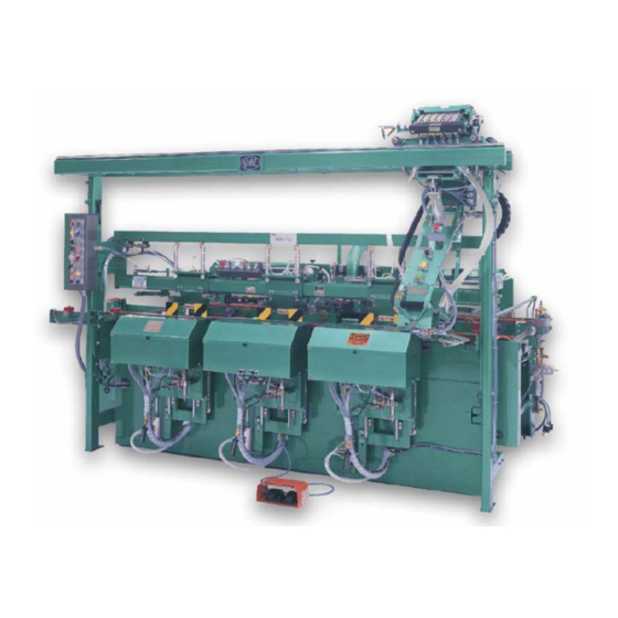
- Page 1 Innovation, Quality & Honesty 990F-3 Pre-Hanging Door Machine Reference Published: September 8, 2006...
-
Page 3: Proprietary Notice
Kval, are intended for use by customers and employees of Kval, and are not to be copied, used, or disclosed to anyone, in whole or in part, without the express written permission of Kval. -
Page 4: Returning Parts Or Equipment To Kval
Returning Parts or Equipment to Kval Kval is happy to help its customer make the most of their investment, and help solve any problems that may occur. When you call, please have the electrical print, air print number, and the serial number of the machine ready, so that we are able to accommodate your needs efficiently. - Page 5 Congratulations on your purchase of a new KVAL 990F-3 This manual is designed with safety in mind. At Kval, our goal is for you to begin safe and fast production with this machine as soon as possible. It is very important that all operators and maintenance personnel read this manual thoroughly.
-
Page 7: Table Of Contents
EGULATIONS : ............................11 PERATORS RAINING : ........................11 THER AZARD ONTROL CTION CHAPTER 3: SPECIFICATIONS ........................13 990F-3 ............................ 13 NCRATING THE 990F-3: ............................. 13 ECEIVING THE : ..........................13 NCRATING YOUR ACHINE : ..........................14 NCRATING ROCEDURE ....................... 15... - Page 8 Off Lock Bore/ Reg. / Deep: ............................. 21 : ..............................21 RILL : ......................21 LATE XTEND : .......................21 HROUGH FOR / J : ..........................21 : ...............................21 : ............................21 ISABLE : ........................21 RONT OUTERS : ..........................21 IDTH DJUST LOSE : ............................21 ISABLE DJUST : ........................22 HIFT...
- Page 9 : ......................32 RELIMINARY INGE ENTER “H” B : ............................32 OSITION LOCKS “H” : ....................33 ENTERING OUTERS WITHIN THE BLOCK : ........................33 ETTING UP THE HINGE BACKSET : ........................34 HANGING THE URRET ETTINGS ................... 35 LATE IDTH LATE OUTER...
- Page 10 Feed System Surging: ............................... 55 Feed system moving doors too fast: .......................... 55 Setting up bolt plate length: ............................56 Lock bore two-stage face drilling: ..........................56 990F-3 S ............................56 HOOTER Six-Shooter keeps running after cycle is completed: ....................56 Hopper Alignment: ..............................
-
Page 11: Chapter 1: Introduction
Chapter 1: Introduction Customer Service Information KVAL is happy to help its customer make the most of their investment, and help solve any problems that may occur. When you call, please have the electrical print, air print number, and the serial number of the machine ready, so that we are able to accommodate your needs efficiently. -
Page 13: Getting Started
Getting Started Your new KVAL Machine arrives at your plant crated, banded, taped and has painted set collars on all shafts; keeping all of the precision moving parts secure during shipping. SEE SECTION “UNCRATING THE 990F-3” FOR INSTRUCTIONS ON UNCRATING AND SET-UP. -
Page 15: Chapter 2: Safety Information
Chapter 2: Safety Information This section contains important safety information. Failure to follow these safety guidelines may subject the operator to physical hazards that may result in serious bodily harm or death. Safety Procedures Responsibility It is the responsibility of each employee to maintain safe working conditions in his or her area. Failure to understand and correctly follow this procedure is direct violation of safety rules and regulations. -
Page 16: Lock-Out And Tag-Out Procedure
The tag shall be destroyed and the lock and key returned to the lockout center. In addition to safety concerns, this policy is required by OSHA regulation 1910.147 and Cal OSHA’S SB198 ruling of July 1991. Lock-Out and Tag-Out Procedure 1. -
Page 17: Accident Situations
ENERGY TYPES—Recognize the Types of Energy to Shut Down 1. Electrical Energy 2. Hydraulic and/or Pneumatic Energy 3. Fluids and Gases 4. Mechanical Energy Accident Situations • Accidental Start Up Equipment can accidentally be turned on and your hands may be in the point of operation or while you are inside. -
Page 18: P-R-O-P-E-R Electrical Lock-Out
P-R-O-P-E-R Electrical Lock-Out P Process Shut Down Open disconnect before pulling the plug. Shut down process or equipment. R Recognize Energy Type Recognize the correct power source. O Off! -Shut Off all Power Controls Shut off machine and electrical energy at both machine and main power switch. There may be more than one source of power and all must be shut off. -
Page 19: P-R-O-P-E-R Fluids And Gases Lock-Out
P-R-O-P-E-R Fluids And Gases Lock-Out P Process Shut Down Shut down process using recommended procedures. R Recognize Energy Type Recognize the material and its hazards. If material is hazardous, use the proper protective equipment. Even water can become a hazardous fluid under high pressure. -
Page 20: Zero-Energy Start Up
P Place Lock-Out Device, Lock and Tag Place lock on the isolating device and sign tag. E Energy - Release Stored Energy Release, spring or tension to achieve, zero energy state. R Recheck Controls and Return To “OFF” Setting Zero-Energy Start Up Zero-Energy State to Start-up to Operating State Starting the equipment is just as important as Lock-Out/Tag-Out in terms of safety. -
Page 21: Safety Guidelines
safe for yourself and your fellow employees. Make sure you follow the P-R-OP-E-R Lock-Out/Tag- Out procedures, and that those around you do also. YOUR LIFE MAY DEPEND ON IT. Safety Guidelines Electrical Electrical circuitry on this machine is protected by an approved lockable disconnect circuit. In addition to this equipment, you must install an approved disconnect for the electrical power supplying this machine Compressed Air:... -
Page 23: Chapter 3: Specifications
8’ doors with four hinges. Change over from one door to another door takes only a couple of minutes and requires no tools. The 990F-3 can be equipped with the optional Six-Shooter to install 3-1/2” X 3-1/2” hinges, as well as the optional Eight-Shooter which can install the 4”... -
Page 24: Uncrating Procedure
Uncrating Procedure: If machine is fully crated remove all the 1” X 6” boards from the crate and the 2” X 4” frame. Move the machine to its approximate location. Carefully cut and remove all banding and tape from part boxes, electrical panel, control panel, buttons, knobs and switches. -
Page 25: Anchoring The Machine To The Floor
When you have set-up and test run your machine to ensure that it is feeding the material properly KVAL recommends anchoring the machine to the floor with ½ Red head, True Bolt Anchors in each of the foot pads. An alternative way to bolting the machine, you may want to use Epoxy and hardened threaded rods to prevent the bolts from vibrating loose. - Page 26 • Standard Anchoring Instructions: * With machine in place and leveled, drill 3” deep holes in the concrete using a 5/8” dia. masonry bit, using the mounting hole as a guide. * Clean out holes with a blowout-bulb or air compressor to ensure that the anchor heads get a firm bite on the walls of the holes.
-
Page 27: Chapter 4: Operation
They are: Auto Run, Maintenance Feed & Width, Maintenance Back Section, Manual Run, and Machine Data. Figure 1: This is the first screen of the 990F-3 which shows the 5 options, Auto Run, Mainenance Feed & Width, Maintenance Back Section, Manual Run, and Machine Data... -
Page 28: Second Screen
Second Screen: When Auto Run is chosen, the second screen appears and displays all the options available to the operator. The main functions such as (R.H., L.H. Disable Auto Feed, Feed Mode and the emergency Stop and start sequence button) are chosen at the center of the machine with a switch. The other commands such as hinge lengths and number of hinges are chosen at this screen. -
Page 29: Fourth Screen
Fourth Screen: When the Maintenance 2 or Maintenance Back Section button is pushed the following screen pops up. This gives you the indicators and eyes of the back section again used with trouble shooting for the machine. The open circles will light up if they are activated. Figure 4: This is the maintenance back section screen this screen shows the eyes for the back section and is also a good trouble shooting point. -
Page 30: Sixth Screen
Sixth Screen: The sixth screen is the Machine Data screen. This screen shows the total number of doors for the machine and the daily total. The reset button will only reset the daily total. When you press the back button it goes back to the main menu screen. Figure 6: This is the machine data screen which shows the total doors ran through the machine and the daily total on the machine the daily total is the only one that can be reset. -
Page 31: Off Lock Bore/ Reg. / Deep
Face Plate Reg /Off / Extend Time: Choose ‘Reg’ to allow the 990F-3 to automatically rout the face plate, select the Extend time when the face plate is longer than 2 1/4”. Use the rheostat located on the backside of the electrical box to control how much time is needed to complete the size of the face plate you desire choose ‘Off’... -
Page 32: Shift Routers Out Of Pocket
Center hinge preparation can be turned on and off with a push pull air valve near the front of the machine. Start Sequence: The ‘Start Sequence’ button starts the 990F-3 cycle of operation after the door and jamb have been clamped in position. Emergency Stop: The ‘Emergency Stop’... -
Page 33: Face Plate Dead Bolt
Face Plate Dead Bolt: Turns face plate on or off Side Drill (Latch Hole) The side drill bit has a 4” long fluted section. For 5” backsets and over bored dead-bolts you’ll need to put in a 6” bit. Be certain the machine is locked out electrically and disconnect air service. Finally, wait until the bit has come to full stop before getting out the collet wrenches. -
Page 34: Controls On The Electrical Box
This button is used if the operator at the 700-C has not reset his machine. The operator of the 990F-3 then can reset the machine so the finished door can then move to the next station (700-C). This button can only be activated if the 700-C: has no door staged with in it The last stage- meaning the out feed wheels have been activated. -
Page 35: Six-Shooter Operating Controls
Emergency Stop: Emergency Stop is used in conjunction with the Reset Button. In the event of crises with the 990F-3 the emergency stop button will only work on the Six- Shooter. Hopper Slide Valve: The hopper slide valve provides the operator a remote air shut-off that controls air flow to the screw hopper to aid in un-jamming debris in the screw drop zone. -
Page 36: Optional Controls
Optional Controls: Load / Unload: If equipped with quick dump hopper (OPTION Z), this button would be used to operate this option. Six-Shooter Gear Installation and Maintenance: Before performing any maintenance or repairs lock and tag out the machine. To remove the gearbox you must first remove the gear motor and plunge cylinder. -
Page 37: Removing The Plunge Cylinder
Removing the Plunge Cylinder: Mark the (4) airlines connected to the plunge cylinder then disconnect. Remove the (4) bolts w/spacers that secure the cylinder to its mounting plates. Remove the 3/4” N.C. nut that fastens the rod end of the cylinder to the front plate of the Six- Shooter carriage. -
Page 38: Removing Gearbox
Removing Gearbox: Slide the Gearbox toward the Six Shooter hand grip. Remove all screw driving bits While supporting the gearbox with a free hand remove the (4) bolts, redi-rods, and spacers that secure the gearbox to its mounting plates. Slide the gear motor mounting plates apart evenly to prevent binding. Gearbox can now be removed. -
Page 39: Gear Box Maintenance
Gear Box Maintenance: Once disassembled and part is replaced, reassemble the gear box as follows: Step 1: Replace the 9 bearings back into proper position as shown in the following picture. Figure 8: Insert each of the bearings in to a proper slot shown in the figure above make sure that the bearings are in good shape. - Page 40 Step 2: Next replace the shafts and gears into the proper bearings as shown make sure the roll pins are in place in the shafts and gears or the shafts will rotate freely without the gears. Figure 9: Making sure that all of the roll pins are placed properly in to the shafts set the shafts in to the bearings from the step above.
-
Page 41: Reinstalling The Gearbox
Step 4: Finally set the other half of the gear box back on top of the shafts aligning the shafts with the output holes on this half of the box. Bolt together accordingly. Figure 11: Making sure that the holes are all aligned Reinstalling the Gearbox: Slide the coupler against the hardened thrust washer on the keyed gearbox shaft. -
Page 42: Front Section
Tighten the set screw nearest to the gear motor against the keyway. Line up gear motor base plate mounting holes with two mounting holes in the mounting plate. Insert the 3/8” bolts and tighten. Re-attach hydraulic lines (A) and (B) to the gear motor Front Section Preliminary Hinge Center Set-Up: During preliminary hinge center set-up you will be positioning the “H”... -
Page 43: Centering Routers Within The "H" Block
Repeat for all routing stations. Setting up the hinge backset: The hinge backset on the 990F-3 is controlled by two turret stops on each of the four routing carriages. The turrets are located at the upper left, and lower left areas on each routing carriage. -
Page 44: Changing The Turret Settings
Changing the Turret Settings: Pull out on the turret plate ( the part that rotates) Continue rotating the turret until the desired bolt color is directly in line with the stop bolt. The stop bolts(s) are located directly below the top turret and directly above the bottom turret set. See following diagram. -
Page 45: Plate Width: Plate Router Vertical Travel
If both the plate and latch hole are off center contact KVAL for instructions on shimming the self centering clamp system. In no case should you adjust the bolts in the turrets since these micrometer set at the factory. -
Page 46: Setting The Doorstops
Setting the Doorstops: The 990F-3 comes equipped with two door stops; one for right hand doors and one for left hand doors. The doors stops accurately position the door so that the hinge locations are consistent. -
Page 47: Door Width Minimum / Maximum Limits
Door Width Minimum / Maximum Limits: The minimum door width on a 990F-3 is 1’ 6”. Depending on various options it could be more than the minimum door width. The limit switch is located on the back section right side edge clamp cylinder bracket. -
Page 48: Setting Up The Back Section
Setting up the Back Section BACK SECTION PLUNGE Before setting up the back section you should test the various assemblies without bits or cutters installed to ensure that everything is functioning properly. Remove the two drilling bits from both the lock bore and the side drills, and back out the plate router so that it won’t drag on the door edge and turn it off using the router switch At the control panel turn on the lock bore and side drills and bolt plate router, and turn the back/front/both selector to back. - Page 49 Once the back section is running smoothly, replace the two drill bits in to the respective collets, turn on and push in the plate router using the Acuflex wrench. Fine a cull door you can ruin and make a practice cut following the next few steps. After the bits have been installed you are ready to put a new chip out in by removing the two 1”...
-
Page 50: Setting Up Lock Height
Setting Up Lock Height: Now that the hinges are in there right places, and your door stops have been set, you can adjust the lock section to put the lock in the right place, relative to the door stop. NOTE: Check door to make sure it is square. It is important that you set the lock height with a good door. -
Page 51: Setting Up Lock Bore Backset
The lock bore backset (the distance from the center line of the lock bore to the door’s edge) is controlled by four adjustable turret stops. KVAL’s factory setting for the lock bore turrets accommodates 5”, 2.75” and 2.375”. See the following diagrams. -
Page 52: Self - Centering Adjustments
Self – Centering Adjustments: This can be done by following the diagram provided. Bolt Plate Width Adjustments: This is done by adjusting the bolt plate width turret and index stop see following diagram. Side Drill (Latch Hole) The side drill bit has a 4” long fluted section. For 5” backsets and over bored dead-bolts you’ll need to put in a 6”... -
Page 53: Lock Bore Diameter
Lock Bore Diameter: Lock out air and electrical service. Use collet wrenches to put in the appropriate face boring bit. Replace chip out block with a new one, or a block previously used for the hole diameter. 40” Lock Location When running a 44”... -
Page 55: Chapter 5: Maintenance
Chapter 5: Maintenance Maintenance Schedule Daily: Blow off dust from entire machine. Lubricate linear bearings and chrome shaft with silicone. Wipe down machine Check tooling for wear Empty water filter bowl if not a self draining system Photo eyes should be wiped off and checked to ensure that all fastening rings are snug. Check the air pressure Check the Chip-Out blocks for wear. -
Page 56: Lubrication Requirements
LDS 18 Special A (KVAL P/N LUBE PD2). Failure to use the approved products voids warranty. Approved Lubrication Products: Chevron AW Hydraulic Oil 32 – or KVAL P/N SYSLUBG or G-C lubricants light AW R&O or Mobile DTE 24 or Shell Tellus32 or Gulf Harmony 32. Lubricator Adjustments: Using knob on the top of the lubricator, adjust until one drop per every other cycle is used (as observed through sight glass.) Turn flow all the way open the reduce flow to proper... - Page 57 To prime the lubricator, find an air line on the Front Section of the machine that is energized, and disconnect it, allowing the air stream to bleed air pressure away from any persons. Direct the air stream at the machine so you can see when there is an oily film blowing out of the air hose. NOTE: It might take up to 15 minutes to get a good prime.
-
Page 59: Chapter 6: Troubleshooting
Chapter 6: Troubleshooting Limit Switches If a machine suddenly stops in mid cycle check the limit switches, a worn limit switch arm or a misadjusted limit switch is more than likely the cause. Depending on the model of limit switch you receive, the amount of “pre-travel” (amount of movement from the arms resting position) is either 5 or 20 degrees before the limit switch actuates (Clicks). -
Page 60: General Air Circuitry Trouble Shooting
The sending and receiving units are in one unit, these operate in the same manner as the ones described previously. Note: When a machine stops for no reason it is usually the fault of dirt photo eye or a misaligned limit switch arm. -
Page 61: To Change Cylinder Retraction Speed
If the valve is not receiving an electrical signal, see “Electrical Trouble Shooting” instruction. It might be necessary to call in a specialist or check with KVAL customer service at 1-800-553-5825 If an Air Leak is coming from an exhaust port on the air bank: Check the solenoid for the manual override. -
Page 62: Basic Electrical Troubleshooting
Basic Electrical Troubleshooting: The electrical component systems are designed to expedite the troubleshooting process and minimize “down time”. In general, component systems have the input or feed functions at the top. Output or load functions are positioned at the bottom. Most two voltage electrical panels are designed with the LOW VOLTAGES on the LEFT, and the HIGH VOLTAGES on the RIGHT. -
Page 63: Front Section Does Not Function Property
Front Section Does Not Function Property: Front section is not turned on at the control panel: The front section will not operate if the front/back/both selector switch at the control panel is not turned to either front or both. Check to ensure that this switch is properly selected. The Six-Shooter is not moved fully to the right: The front section will not operate if the Six-Shooter has not been rolled all the way to the right at its home position and makes contact with the limit switch located at the upper right corner of the... -
Page 64: Cylinders That Move The Front Section
Cylinders that move the front section Move front section to the “In Pocket Position”, then do the following: Check to ensure that the 8” and 1 7/8” cylinders are all fully extended. Check to ensure that the 1-1/4 cylinders are fully retracted. One of the cylinders is malfunctioning: Check each cylinder on each front section assembly, looking/ listening for air leakage from the seals, connecting air lines, valve bank that operates the cylinder or cylinder stack. -
Page 65: One Or More Through-Beams Are Malfunctioning
Feed System Surging: If the feed system surges at high and low speed, it usually means that the IR comp on your DC drive board needs to be adjusted. Call a KVAL technician for more information. Feed system moving doors too fast: If the feed system is moving doors into the door stop to fast check the DC drive board. -
Page 66: Setting Up Bolt Plate Length
Minimum speed should be set to a smooth crawl. Setting up bolt plate length: The 990F-3 is capable of machining bolt plates 2” to 12” long. To adjust the bolt plate length simply adds or removes telescoping spacer pins as required. Make sure that the same amount of spacer pin is added to both the left and right sides. -
Page 67: Hopper Alignment
Hopper Alignment: Shut off the slide valves, located on the Bimba O91-D cylinder, that prevents screws from dropping down. Push the Six-Shooter start and pivot down to the right hand “H” block. Once you adjust the collars, push the release button to pivot back the Six-Shooter. Try rolling it from one end of the frame to the other if it doesn’t roll freely, loosen the set collars on one axel and twist the lower carriage left and then right until it will roll freely, making sure that the rollers are aligned and there is no binding. -
Page 68: Hinge Laps Side Of Pocket Or Screws Pulled Sideways
Place a hinge on the magnetic hinge holder with the knuckle centered between the two small stop bars in the slot, push “Start” to pivot it into the first “H” shaped block followed by “Screw Insert” to mount the hinge. When the driver bits stop, push the “Release” button and inspect the screw pattern. -
Page 69: All Four Hinges-Bit Marks Too High Or Too Low
All four hinges-bit marks too high or too low: If all four are too high or low by the same amount you need to raise or lower the 6 shooter. Measure how much the marks vary from center, shut off the slide valves on the screw feeder to prevent screws from dropping out, roll the 6 shooter to the end of the machine. -
Page 70: Speed Of Six-Shooter Going In
If the speed of the bit rotation is changed, the cylinder speed in will probably also have to be changed. Normally the bypass valve is set at the factory and should not be adjusted without calling a KVAL technician. Loose Screws All Screws Loose: The Six Shooter is designed to drive screws tight, just like a hand drill. -
Page 71: Kick-Out
See ‘Loose Screws’, and re-adjust the stop bolt that trips the limit switch (on the right side of Six Shooter), turning the Six Shooter off as the screws bottom out. Check and see if the split shells are too tight. See ‘Split Shells’ Kick-Out: Kick out is what happens when you are driving screws and the Six-Shooter kicks out of the “H”... -
Page 72: Magnetized Screws
Magnetized Screws: Sometimes screw manufacturers fail to demagnetize screws before sending them to you. Have your purchasing agent make sure that they are sending demagnetized screws so they will slide freely against the metal within the screw feeder. Make sure the slides in the screw feeder, plastic feeder tubes, and the screw receivers are thoroughly clean. -
Page 73: Hinge And Screw Quality
Any lesser quality can wear the split shells out and sacrifice screw driving quality. In order to insure that all screw hoppers installed on KVAL machines work correctly to customer specifications, KVAL requests each customer to send 600, or approximately one box, of screws for testing prior to the machine being shipped from the factory. -
Page 75: Warranty
The decision to repair or replace machinery parts under warranty is subject to review of said machinery parts by an authorized KVAL representative and will only be performed if determined by KVAL that part qualifies for repair or replacement as specified in this warranty. -
Page 77: Bills Of Materials
BIM CYL 091 1 SINGLE ACTING FRONT NOSE MOUNT 1-1/16 BORE. BIM091 ;9BB01;8CD; BIM CYL 095D 5 DOUBLE ACTING FRONT NOSE MOUNT 1-1/6 BORE. BIM095D ;9BB01;;8CD;; CHIPOUT,HINGE SECTION (990F-3) 1-1/4 X 1-1/2 X 4-1/2 SPRING LOADED,ASSY. CHIPOUT09 BIN ;1HB;;;;; FAB HDW 221-1D PIVOT MOUNT FOR 221-SERIES PANCAKE CYLINDERS. FAB2211D ;9BB03;8EB;;;;... -
Page 78: Option R1 - Back Section
OPTION R1 – BACK SECTION KVAL P/N QTY PART DESCRIPTION ADV960A9Z 2 ADV CYL 960 X 8 DC. BIN ;9BC02;8CC;;;; ADV960M01 2 ADV HDW 960 ROD CLEVIS.(BRC-100) BIN ;9BC02;8CC;;; ADV HDW 960 CLEVIS MT DOUBLE W/PIN & CLIPS (B960CM). ADV960M02 ;9BC02;8CC;;;... -
Page 79: Frame Section
BIN ;;;;;; 1-1/4 DIA 5/16-24 THD RTR BIT SPIN ON #EMB-114X (990-F3 FRONT). EVE85238 ;9AA;;;;; CYL ASSY 990F-3 & 4 HINGE SECT VERT CYLINDER ASSEMBLY.(D521XP14XX & E521XP14XX & ADV490A3H) WITH 1/4 FLOW CONTROLS. (USED ON FAB-A009 MACHINES AFTER (05/00). BIN ;9BB03;;;;;... - Page 80 INDXS0303106 (XS03031-06). BIN ;;;;;; ARBOR 1/2DIA SHK 1/4-28 THD 2-3/8 OAL BACKSECTION W/1 HP PERSKE MTR. KVARBOR18A1 BIN ;9CG;;;;; ARBOR 1/2DIA SHK 5/16-24 THD 2-1/16 OAL 990F-3 HINGE RTR W/PERSKE KVARBOR18B1 2HP. BIN ;9CG;;;;; LIN400001 5 CONNECTING LINK 40 CHAIN.
-
Page 81: Head Section
40:1 RATIO RIGHT ANGLE (2Z952) SPEED REDUCER 43 RPM WINSMITH 920 WIN920WU4M WN-LR (MOD.FOR WIDTH ADJ.). BIN ;;;;;; HEAD SECTION KVAL P/N PART DESCRIPTION BIM CYL 090.5D 1/2 DOUBLE ACTING FRONT NOSE MOUNT 1-1/16 BORE. BIM090UD BIN ;8CD;9BB01;;;; BIM CYL 122DP 2 DOUBLE ACTING REAR PIVOT DOUBLE END MOUNT 1-1/4 BIM122DP BORE. -
Page 82: Back Section
BACK SECTION KVAL P/N PART DESCRIPTION 0832CFS037 8 FLAT HEAD 8-32 X 3/8 SOCKET CAP SCREW GRADE 8. BIN ;5AB;;;;; BACK SECTION,MAIN,CLEVIS,FREE MACHINE STEEL,3/4 X 3/4 X 2. 15-00-Y ;;;;;; BACK SECTION,MAIN,CLEVIS,FREE MACHINE STEEL,7/8 X 7/8 X 1.650. 15-00-Z ;;;;;;... - Page 83 N4D1F IDLER FLAT FACE 4-3/8-OD 1 BORE 1-1/16 FACE 2-1/8 SHAFT. BRON4D1F ;;;;;; CHIPOUT BACK SECT LOCK BEVEL 5/16 X 3-1/2 X 4" RYERTEX. BIN ;09B; CHIPOUT05 9HB ;;;;; 7/16-20 X 1-1/4 LONG THREADED COUPLER HEAVY DUTY (SUB ASSEMBLY). CPLR0720-HD BIN ;8AX;;;;;...
-
Page 84: Screw Changing Hopper
BIN ;9CC;;;;; WRENCHER32 1 WRENCH FOR THE ACURA-FLEX NUT (04616) SCREW CHANGING HOPPER KVAL P/N PART DESCRIPTION AKR30230 1 5-1/2 WIDE YELLOW BIN (5W871) 10-7/8 DEEP 5 HIGH (30-230). BIN ;8AX;;;;; BIM CYL 126DP 6 DOUBLE ACTING REAR PIVOT DOUBLE END MOUNT 1-1/4 BIM126DP BORE. -
Page 85: Six Shooter
SIX SHOOTER KVAL P/N PART DESCRIPTION 6 SHOOTER,CARRIAGE,ASSY TRAVEL CARRIAGE WHEEL. 13-00-23 ;7AA;9DB04;;;;; 6 SHOOTER,MAIN,CONTROL MOUNTING PLATE,Hot Roll,1/4 X 8 X 8 3/4. 13-00-AM BIN ;7AA;;;;; 13-00-AZ 1 6 SHOOTER,CARRIAGE,Angle Iron,1/4 X 2 X 2 X4 1/2. BIN ;7AA;;;;; 13-00-CH 1 6 SHOOTER,CARRIAGE,Angle Iron,1/4 X 3 X 5 X 3. -
Page 86: Eight Shooter
HYD OIL, (FLYINGAAW32) 1 GAL CONTAINER (LUBRICATOR & HYD SYSLUBG PUMP OIL). BIN ;9GG;1UB;;;; EIGHT SHOOTER KVAL P/N PART DESCRIPTION 03L388 2 HYD HEX UNION 3/4-16 THD 1/2 TUBE 37-DEG JIC FLARE (03L3-8-8). BIN ;;;;;; HYD 45 DEG ELBOW 3/4-16 MALE FLARE TO 3/4-16 FEMALE SWIVEL (3703-8-8). - Page 87 Gage, Pressure Gage, 1 1/2", 1/8 NPT (Nycoil G36-10-01) (SUB: SMCK10) NYCG361001 BIN;9CD01: SMCNVSA03 1 SMC VLV NVSA4114-000 1/4 BASE VALVE 4-WAY PILOT. BIN ;9CD01;8CE;;;; SMC VLV NVSA4214-000 1/4 BASE VALVE 4-WAY DOUBLE PILOT. SMCNVSA06 ;8CE;;;;;...
-
Page 89: Notes
NOTES Kval Inc. 825 Petaluma Blvd So. Phone (707)-762-7367 • Fax (707) 762-0485...
Need help?
Do you have a question about the 990F-3 and is the answer not in the manual?
Questions and answers