
Related Manuals for Kval Commander III


Summary of Contents for Kval Commander III
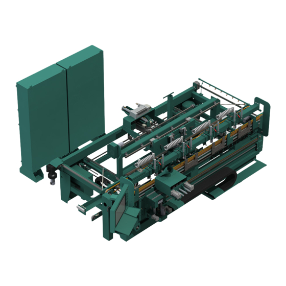
- Page 1 Service Manual Published:10/9/19 Innovation, Quality & Honesty Commander III Door System With KvalCam...
- Page 2 Proprietary Notice This Manual is confidential and contains proprietary information and intellectual property of KVAL Inc., and is to be used solely by Customer as an operating manual for KVAL Inc. machines. Neither this Manual nor any of the information contained herein may be reproduced or disclosed under any circumstances without the express written permission of KVAL Inc.
- Page 3 KVAL Commander III Service Manual Your Feedback is Welcome: To help us design products that make your job easier and your business more successful, we'd like to gain your perspective about your user experience with our product - that is, the manual, the machinery, the software, etc.
- Page 4 LICENSE. IF YOU DO NOT AGREE TO ALL OF THE TERMS OF THIS LICENSE, THEN DO NOT USE THE KVALCAM SOFTWARE. KVAL, Inc., is the owner of all rights in respect of the software and documentation (referred to as “Licensor”). You are the purchaser of KVAL Machinery operated by the KVALCAM Software are the “Licensee”.
- Page 5 KVAL Commander III Service Manual KVAL Commander III Service Manual...
-
Page 6: Table Of Contents
Table of Contents Introduction to the Commander III Chapter 1 Chapter 1 at a Glance.............. 1-1 Overview of the Commander III System ........1-2 Table of Options...................1-3 About this Manual .................1-5 Safety Sheet Sign-Off Sheet..............1-5 Safety First!................1-6 Safety Sheet Sign-Off Sheet..............1-6 Safety Terminology of Labels..............1-6... - Page 7 About Taper Bearings .................3-18 Tapered Bearing Housings ..............3-18 Ball Screw Nut ..................3-19 Ball Screw Drive Assembly..............3-19 Pulley and Idler Shafts................3-20 Sample of Grease Locations for the Machine......3-21 Front Section Servo Assemblies............3-24 Grease Locations Cutter Head ..........3-25 Commander III System...
- Page 8 Important Notice about Adjusting Cylinder Speed ......4-14 Adjusting Cylinder Extend Speed ............4-14 Adjusting Cylinder Retraction Speed ..........4-14 About Switches and Sensors........... 4-15 Using Sensors to Trouble Shoot ............4-16 Troubleshooting Electrical Problems ........4-17 If the Power Stops During Normal Operation........4-17 KVAL Commander III Service Manual...
- Page 9 Control Power Light OFF ..............4-20 Overload Relay Light OFF ..............4-21 E-Stop Light OFF ................4-21 Stop Light OFF ...................4-21 Start Light OFF ...................4-22 24VDC Light OFF ................4-22 Network System Overview............4-23 Connections to Servo Drives ..............4-23 Connections to VFD’s (High Freq Panel)..........4-23 Commander III System...
- Page 10 Notes:...
-
Page 11: Introduction To The Commander Iii
Chapter 1 at a Glance The following information is available in this chapter Section Name Summary Page This section provides an overview of the Commander III. page 1-2 Overview of the It includes a general description and a table of available Commander III... -
Page 12: Overview Of The Commander Iii System
• Door hand indicator light to speed processing in a companion 700C door framer. Operators Interface: The operator interface for the Commander III is simple and requires very minimal training to cre- ate door specifications. Dimensions are entered at the amply sized 19” Beckhoff touch screen for hinge layout from the door top, hinge reveal, hinge size, ¼”radius, 5/8”radis or square corners,... -
Page 13: Table Of Options
Beckhoff servo motor and drives. This makes remote support and program updates easier than ever before. A connection to the internet is required for remote support from Kval, which can remain physically disconnected except when needed. Software is pre-installed to mon- itor all machine functions from our offices in Petaluma when required. - Page 14 Overview of the Commander III System Option Title Description Option Best 93K (Cylindrical) Gearbox See Above (Option W) with Air motor Option Schlage “D” Serial #792 Drill See Above (Option W) Gearbox with Air motor Option Yale 80-7150-0047-010 Drill See Above (Option W)
-
Page 15: About This Manual
Overview of the Commander III System About this Manual This manual is part of a package delivered with the machine line. Integration Package includes the following: includes the following: Operation Manual Chapter Title Description Introduction Descriptions of Machine Line and Safety Information. -
Page 16: Safety First
See “Safety Sign-Off Sheet” on page 1-21. Safety Terminology of Labels In addition to the nameplate, KVAL machines may have other warning labels or decals that pro- vide safety information to operators. Safety labels should be clearly visible to the operator and must be replaced if missing, damaged, or illegible. - Page 17 Before performing any mainte- nance or repairs on this machine turn off the main air disconnect. Lockout and tagout this connection. See “Lockout Tagout Procedure” on page 1-10. KVAL Commander III Service Manual...
- Page 18 This should be done in accordance with applicable state and/ or federal code requirements. KVAL Commander III Service Manual...
- Page 19 Safety First! Compliance with Codes and Regulations KVAL advises that you request an on-site state safety review of your installation of this machine. This is to ensure conformance to any additional specific safety and health regula- tions which apply in your geographic area.
-
Page 20: Lockout Tagout Procedure
OFF position. Then pull out the red tab and place a padlock through the hole. Place your tag on the padlock, as per the tagout guidelines below. KVAL Commander III Service Manual 1-10... - Page 21 • If more than one person is working on the machine, then each additional person places a lock and tag on each disconnect. • Only each operator may remove their own lock and tag. KVAL Commander III Service Manual 1-11...
-
Page 22: Follow The P-R-O-P-E-R Lockout Rule Of Thumb
O..OFF! Shut off all power sources and isolating devices P..Place lock and tag E..ENERGY: Release stored energy to a zero-energy state R ..Recheck controls and test to ensure they are in the “OFF” state KVAL Commander III Service Manual 1-12... -
Page 23: Zero-Energy To Start-Up
Replace Guards Replace all equipment guards. If part of equipment cannot be properly adjusted after start-up with guard on, contact the KVAL Service team. See “Getting Help from KVAL” on page 1-15. Check Controls Confirm that all switches are in the “OFF”... - Page 24 Be sure to follow the P-R-O- P-E-R lockout/tagout procedures, and that those around you do also. Close the Cage Gate Verify all cage gates are securely closed. Ensure all safety protocols are in effect. KVAL Commander III Service Manual 1-14...
-
Page 25: Getting Help From Kval
• Outside the U.S. and Canada, call (707) 762-7367 or fax (707) 762-0485 • Email address is service@kvalinc.com • Hours: 6:00 AM to 4:00 PM Pacific Standard Time, Monday through Thursday 6:30 AM to 1:30 PM Pacific Standard Time, Friday KVAL Commander III Service Manual 1-15... -
Page 26: On-Line Help
Product Return Procedure If you’ve contacted Kval for help and it is determined that a return is necessary, use the procedure below to return the machine or part. Note: Non-Warranty returns are subject to a 15% restocking charge. -
Page 27: How To Download The Service Application
Download Application To download the application, go the KVAL website ( http:// www.kvalinc.com At the KVAL website, select the tab. Follow the instruc- Support tions on the Support web page. Click the Download button to download the application that... - Page 28 Session code: An internal number to track this machine. It is auto filled. Your Name Field: Enter your name. The KVAL techni- cian will use this field to identify this machine. Description: Enter machine Serial number and issue.
- Page 29 How to Download the Service Application Page Intentionally Left Blank KVAL Commander III Service Manual 1-19...
-
Page 30: Safety Sign-Off Sheet
Name (print):__________________Signature: __________________ Date:____/____/___ Note: It is recommended you make a copy of this sheet for new operators. If a copy is needed, you may download a PDF at the KVAL website ( http://www.kvalinc.com You may also contact our Service Department at (800) 553-5825 or email at service@kvalinc.com. - Page 31 Safety Sign-Off Sheet KVAL Commander III Service Manual 1-21...
-
Page 32: System It Administration
The controller is an on board computer KVAL Commander III that supplies the user interface and controls the operation of the machine. With the controller, KVAL can remotely help troubleshoot your machine. Chapter 2 at a Glance Section Name... -
Page 33: About The Commander Iii Computer
Service Support will be able to access your machine through your company’s Intranet and help solve any issues that may occur. Connection to the Intranet is achieved by interfacing with the Commander III controller. The location of the Intranet connection is identified in the figure below (RJ45 to Intranet.) About the Commander III Computer ®... -
Page 34: About Backing Up The Data
About Backing up the Data About Backing up the Data Right Click the KVAL Icon at the bottom of the screen to display this menu. Note: Select icon from the windows screen and drag to the favorites bar for access to this icon. -
Page 35: About Remote Connection To Kval Service
Remote access is a powerful tool to help fix issues that occur with this machine. With the remote access, our KVAL service technician is able to observe your user screen in real time, read and adjust programming code. See “Getting Help from KVAL” on page 1-15, for more information. - Page 36 Notes:...
-
Page 37: Maintenance Of The Commander Iii
This chapter describes preventative maintenance steps for . The content is KVAL Commander III geared to guide technicians to keep a regular maintenance schedule for your KVAL machine. Keeping your machine maintained is an important piece for successful operation of your KVAL door production process. -
Page 38: Maintenance Schedule
This should be done in accor- dance with applicable state and/or federal code requirements To view a video of the maintenance process, visit the KVAL website. Select the Video Tab to view videos. http://www.kvalinc.com/... - Page 39 Inspect all nuts and bolts for tightnesses Tighten is necessary. Inspect Check that there is a smooth transition with a door feeding into and out of machine. Backup computer software. Back-up Clean Wash filter and lubricator bowls with soapy water. KVAL Commander III Service Manual...
-
Page 40: 300 Cycle Maintenance Steps
Use pressured air to blow off dust and debris on entire machine. Use a clean rag to clean areas not affected by pressurized air. Also blow out any dust collection units. Check vertical bearings for loose screws. Loose screws could cause bearing damage. High Dust Accumulation Areas KVAL Commander III Service Manual... -
Page 41: 600 Cycle Maintenance Steps
Slide locking switch down to unlock twist trap to remove. Reverse action when installing trap. Inspect Tooling Inspect the Tooling for wear, (Drill Bits, Cutting Tools) See “Remove and Replace the Router or Pre-Drill Bits” on page 3-33 . KVAL Commander III Service Manual... -
Page 42: Empty Dust Collection Units
Check and empty any dust collection units. Clean any dust filters. Dust collection systems vary from machine to machine. Follow manufacturers directions to empty dust collection units. Filters Dust Collection Containers Typical Dust Collection Unit FIGURE 3-2. KVAL Commander III Service Manual... -
Page 43: 3,000 Cycle Maintenance Steps
(clicking sound) when moved to the extreme. Note: Depending on the model of limit switch, the amount of “pre-travel"(amount of movement from the arms resting position) is either 5 or 20 degrees before the limit switch actuates. KVAL Commander III Service Manual... -
Page 44: Inspect Airlines
Not all machines have lubricator option installed. Check your machine or Air prints to verify installation. Ensure Air is turned off. Refill all lubricators. Replace fluid if milky or discolored. Use ab ISO 32 stan- dard hydraulic oil (KVAL PN: SYS- LUBEG). Slide locking switch down twist bowl and remove. Refill bowl. Reverse action when installing trap. -
Page 45: Grease Ball Screw Bearings
For locations to lubricate, see “Grease Ball Screw Bearings” on page 3-9. Clean Bearing Shafts Clean all bearing shafts with clean, dry cloth. Spray shaft with silicone oil and clean build up grime and dirt. KVAL Commander III Service Manual... -
Page 46: 12,000 Cycle Maintenance Steps
Not all machines have lubricator option installed. Check your machine or prints to verify installa- tion. Inspect hydraulic lines for loose fittings, leaks and cracks. Inspect hydraulic lines from the source to the end assembly. KVAL Commander III Service Manual 3-10... -
Page 47: Inspect Ball Rail Shafts And Ball Screws
Example of a Pitted Ball Rail Example of a Pitted Ball Screw Clean and Lubricate Slides, Cylinder Rods and Bearing Shafts Clean and lubricate all slides and cylinder rods with dry silicone spray. KVAL Commander III Service Manual 3-11... -
Page 48: 72,000 Cycle Maintenance Steps
Shutdown the machine and follow the “Lock Out Tag Out procedures Check all connections in each node box and electrical panel. Wires may become loose due to vibration. KVAL Commander III Service Manual 3-12... -
Page 49: Computer Backup
• Slide lock down to unlock. • Twist bowl to remove it. • Remove filter from Air filter assembly. Inspect and clean or replace if necessary. • Clean bowls and reas- semble. KVAL Commander III Service Manual 3-13... -
Page 50: Maintenance No-Goes
• Do not remove shim stock • Do not Change or Alter any safety assemblies (E-Stops, Gate Locks, etc) • Do not Change programs in PLC’s or PC’s • Do not Alter Electrical Components KVAL Commander III Service Manual 3-14... -
Page 51: Lubrication Schedule
Lubrication Schedule Lubrication Schedule KVAL recommends the following lubrication schedule to ensure that the machine operates prop- erly. Recommended Lubrication Schedule TABLE 3-2. Type of Recommended Schedule Recommended Assembly Lubrication Type Linear Bearing Pillow Block Bearing Every 250 Hours of Machine Operation... -
Page 52: Lubrication Requirements
Hub Style Opened Pillow Block parallel perpendicular mount Greasing Approximatively 1 Gram (one pump from grease gun) of Dura-Lith Grease (KVAL P/N: Lube EP-2). Every 250 hours of operation. Pillow Block Bearings FIGURE 3-3. KVAL Commander III Service Manual 3-16... -
Page 53: Flange Bearing Housings
X,Y, or Z direction. Greasing Ball Rail Bearing Approximatively 1 Gram (one pump from grease gun) of Dura-Lith Grease (KVAL P/ Every 250 hours N: Lube EP-2). of operation. Ball Rail Bearings FIGURE 3-5. KVAL Commander III Service Manual 3-17... -
Page 54: About Taper Bearings
To identify a , look at the enclosure and verify there are seals Tapered Bearing Housing between the screw and the housing. Tapered Bear- ing Housing Tapered Bear- ing Seals Tapered Bearing Housing FIGURE 3-7. KVAL Commander III Service Manual 3-18... -
Page 55: Ball Screw Nut
Ball Screw Nut Recommended every 80 Hrs Servo Motor Pillow Block (Hub Style Recommended every 250 Hrs Tapered Bearing Housing Recommend One Pump 4 X a Year Maximum Ball Screw Drive Assembly FIGURE 3-9. KVAL Commander III Service Manual 3-19... -
Page 56: Pulley And Idler Shafts
Breakout of Pulley Assembly Pulley in Action Grease IN Note: It is important not to overfill the Idler Shaft. Avoid getting excess grease on the belts Grease Out Idler Shaft KVAL Commander III Service Manual 3-20... -
Page 57: Sample Of Grease Locations For The Machine
Grease Needle Nozzle Outfeed Stop Servo Assembly Lock Location Servo Assembly Carriage X Axis Assembly Carriage Z Axis Assembly Carriage Position Servo Assembly Carriage Y Axis Assembly Top View of Commander III FIGURE 3-10. KVAL Commander III Service Manual 3-21... - Page 58 Recommend One a Pump4 X a Recommended Year Maximum every 80 Hrs Ball Screw Nut Recommended every 80 Hrs Servo Motor Pillow Block (Hub Style Recommended every 250 Hrs Servo Motor Assembly Bearings FIGURE 3-11. KVAL Commander III Service Manual 3-22...
- Page 59 Pillow Block (Hub Style Recommended every 250 Pillow Block (Hub Style Recommended every 250 Hrs Located on the cutting side of the machine. Recommend using an extender to grease the hub. Servo Motor Assembly Bearings FIGURE 3-12. KVAL Commander III Service Manual 3-23...
-
Page 60: Front Section Servo Assemblies
Recom- Tapered Bearing Housing Tapered Bearing One Pump 4 X a mended Recommend One Pump 4 X a Housing Year Maximum every 250 Hrs Year Maximum Recommend One Pump 4 X a Year Maximum KVAL Commander III Service Manual 3-24... -
Page 61: Grease Locations Cutter Head
Moves the entire head in the X axis direction assembly in the Y axis direction 2 rails 2 bearings top rail, 4 bearings bottom rail 2 rails 3 bearings per rail Front View Cutting Head FIGURE 3-13. KVAL Commander III Service Manual 3-25... -
Page 62: Cutting Head Tools
1 rail 2 bearings tool 2 rails 2 bearings per rail 2 rails 2 bearings per rail Front View Cutter Box FIGURE 3-14. KVAL Commander III Service Manual 3-26... -
Page 63: Back Section Grease Points
Below is a view of the Back Section Assembly Use an extender to reach tight areas. Vertical Ball Rail Bearings Lubricate Pulleys Set of two assemblies ’4 Bearings 4 Rails Ghosted View of Machine Frame FIGURE 3-15. KVAL Commander III Service Manual 3-27... -
Page 64: Grease Location On The Frame (Feed System)
InFeed Clean and Lubricate feed system Lubricate Pulleys hex shaft with Silicon Spray Includes Hub Bearings on Axel Ghosted View of Machine Frame FIGURE 3-16. KVAL Commander III Service Manual 3-28... -
Page 65: Air Input With Lubrication
The clean dry air is diverted to blow off nozzles. The lubricator, located after the CDA filters, delivers the lubricated air to valve banks and air cylinders. There are two types of air inputs on KVAL machinery. Not all machines have lubricator option installed. Check your machine or Air prints to verify installation. -
Page 66: Air Line Without Lubricator
The air input system takes in shop air and supplies clean dry air (CDA). Shop Clean Dry Air (CDA) to Air Blow Off Input Air On- Off Knob Muffler Air Distribution Block Pressure Gauge with adjust Filter (purge) Air Filter without Lubricators FIGURE 3-18. KVAL Commander III Service Manual 3-30... -
Page 67: Replacing Bits In The Front Section
This section describes the steps to change the pre-drill bits, router bits, and chisels in the heads on the front section., shows the locations of the replaceable parts inside the heads Chisels Chisels Pre- Drill Bit Router Bit Counter Rotate Router Location of Bits in the Commander III Heads FIGURE 3-19. KVAL Commander III Service Manual 3-31... -
Page 68: Inspect And Clean Collet Assembly
FIGURE 3-20. How to Access to Bit Assemblies Shutdown the machine and follow the “Lock Out Tag Out procedures. After machine is locked and tagged out, loosen remove the screws from the Top Dust Cover. KVAL Commander III Service Manual 3-32... -
Page 69: Remove And Replace The Router Or Pre-Drill Bits
Tighten the collet assembly. Router Depth Set to 1 3/4 “ Drill Depth Set to 2.0” 1 3/4 ““ 2.0 “ Router Bit Depth Gauge Setting the Bit Depths FIGURE 3-22. KVAL Commander III Service Manual 3-33... -
Page 70: Remove And Replace The Chisels
Slide in the new chisels. Tighten bolts back and forth until the bracket is tight. Inspect and verify the work. Clean the work area. If maintenance is completed, replace dust cover and tighten bolts. KVAL Commander III Service Manual 3-34... -
Page 71: Replacing Tooling In The Back Section
Replacing Tooling in the Back Section Replacing Tooling in the Back Section The Commander III is a powerful electro-mechanical Caution motion control system. If servicing the Commander III follow the safety guidelines described in. Failure to do so can result in damage to equipment and/or seri- ous injury to personnel. -
Page 72: Changing The Bolt Drill
Changing the Face Plate Drill The motor/drill combination is the same as the predrills and routers. Follow the Hinge Head same steps as detailed in See “Remove and Replace the Router or Pre-Drill Bits” on page 3-33. KVAL Commander III Service Manual 3-36... -
Page 73: Option W: Replacing Function Drill Assembly
Insert the new assembly (repeat steps 3,2,1) • Secure replacement assembly with the two bolts • Tighten the two bolts. • Re-engage belt drive assembly. • Pull back motor until belt is secure • Tighten lever KVAL Commander III Service Manual 3-37... -
Page 74: Collet Torque Values
Collet Torque Values Collet Torque Values KVAL recommends torquing the collets. Torquing adds consistency is important for repeatable machining. Follow the torque tool manufacturers method of torquing. KVAL Commander III Service Manual 3-38... - Page 75 Collet Torque Values KVAL Commander III Service Manual 3-39...
- Page 76 Collet Torque Values KVAL Commander III Service Manual 3-40...
-
Page 77: Troubleshooting The Commander Iii
Troubleshooting the Commander III This chapter describes troubleshooting steps to help technicians solve issues that may occur with your KVAL machine. If help is needed, call or contact our KVAL Service team at (800) 553-5825 or http://www.kvalinc.c Get Live Technical Help Chapter 4 at a Glance The following information is available in this chapter. -
Page 78: About Motion Control
KVAL Machinery. Sequencing: Sequencing is a series of events executed in a predetermined order. Most KVAL machines use a form of sequential motion control. A typical series of events for a KVAL machine are: Move the door into position. -
Page 79: Basic Control Circuit
• Moves the load. Examples: A motor or a pneumatic cylinder. The Position Feedback. • Provides location information to the controller. Examples: A limit switch, a photo eye, or ferrous eye, a resolver or an encoder KVAL Commander III Service Manual... -
Page 80: About A Typical Contactor Control
Common DC - Thermal Control Coil for OverLoad 120 Vac. Should measure Line Voltage here Motor Schematic Drawing of Contactor and Thermal Overload Block Diagram of a Common Contactor Circuit FIGURE 4- 25. KVAL Commander III Service Manual... -
Page 81: About Contactor Troubleshooting
If the same overload keeps tripping, verify condition. Follow circuit path using the E-Drawing as a reference. a.Common issues: Check for bad wire, bad motor, or if load is too great for cur- rent draw. KVAL Commander III Service Manual... -
Page 82: About Typical Vfd Motor Drive Control
An adjustable-speed drive is used to control the motor speed and torque by varying motor input frequency and voltage. A variable-frequency drive (VFD) is used in KVAL machinery to accu- rately drive motors for machining or moving product through the machine. The figure below shows a block diagram of a typical motor drive circuit. -
Page 83: About The Vfd
Figure 4- 27 on page 4- VFD models vary in KVAL machines depending on where it is used, voltage requirements and type of PLC used. This is a general view on the VFD. See the machine’s Electrical Print for detailed information. -
Page 84: About Vfd Troubleshooting
Note: The number of reset buttons depends on the machine type and option. The fig- ure above shows a machine with 11 VFDs The VFD manuals are located in the Electrical Panels. On some machines, documentation can be found in the operation station in the documen- tation folder. KVAL Commander III Service Manual... -
Page 85: About A Typical Pneumatic Circuit
Note: In this sample set-up, Port A is nor- mally open and Port B is nor- mally closed. If power is OFF, air should be on Port B. Block Diagram of a Pneumatic Circuit FIGURE 4- 30. KVAL Commander III Service Manual... -
Page 86: Typical Pneumatic Assembly
About a Typical Pneumatic Circuit Typical Pneumatic Assembly Pneumatic assembly setups vary in KVAL machines depending on where it is used and air requirements.This is a general overview of a pneumatic assembly. See the machine’s Air Print for detailed information. -
Page 87: About Cylinder Operation
Control Valve pressed air to extend port of the Cylinder are extended deactivating the Cylinder Router Retract Sensor fully extends activating the Router Extend Sensor. KVAL Commander III Service Manual 4-11... - Page 88 Control Valve Cylinder. retract deactivating the Cylinder Router Extend Sensor When the are fully retracted, the is activated. Cylinder Router Retract Sensor senses the voltage from the completing the process Retract Sensor KVAL Commander III Service Manual 4-12...
- Page 89 Router Assembly (Load) Retract Sensor Activated Air Pressure Retracts Cylinder Cylinder and Router Assembly Air In Control Valve Position Feedback Extended Sensor: Deactivated Translated Positioning Retracted Sensor: Force Instructions Activated Retracted 0 Volts Positioning Load System KVAL Commander III Service Manual 4-13...
-
Page 90: Important Notice About Adjusting Cylinder Speed
Adjusting Cylinder Retraction Speed Tip: If Installing a new flow control assembly, shut down the flow control and back out 4 to 5 turns. this position is a good starting point for kine adjust. KVAL Commander III Service Manual 4-14... -
Page 91: About Switches And Sensors
PLC. When the metal object leaves the sensing area, the sensor to returns to 24VDC and sends it to the PLC. • As a result, if a metal object is sensed, the output of the sensor equals 0VDC Sensors on Piston and Cylinder KVAL Commander III Service Manual 4-15... -
Page 92: Using Sensors To Trouble Shoot
• Check the output voltages of the sensors in inactive mode.The voltage should effec- tively equal 24 VDC The distance from an eye to the door should be in range. Typically the range should be 3/4'' to 7/8'' from the top of all eyes to the door. KVAL Commander III Service Manual 4-16... -
Page 93: Troubleshooting Electrical Problems
Refer to Air and Electrical Schematics provided with delivery of the machine. Schematics are located in the Electrical Panel. If copies NOTE: are unavailable, contact the KVAL Service Department. Have model number and serial number of machine readily available. Warning The following checks require the electrical panel to be energized. - Page 94 Note: Most electrical problems are related to mechanical malfunction (e.g., stuck motors, jammed chain, blocked photo sensors etc.) Note: If a solenoid valve is suspected, and not cleared in the air checks section (see), it can be electrically jumped to check operation. KVAL Commander III Service Manual 4-18...
-
Page 95: Troubleshooting With The Status Light Panel
STEP 4: Stop (Amber) If light is OFF go to item on page 4-21. STEP 5: Start (Amber) If light is OFF go to item on page 4-22. STEP 6: 24VDC (Green light is OFF go to item on page 4-22. KVAL Commander III Service Manual 4-19... -
Page 96: Control Power Light Off
If no power on the output side, and there is power going into the top of the Control Transformer, replace the Control Transformer. If there is power at the Control Transformer, check the wiring of the black and white wire going from the Control Transformer to the 110 VAC Terminal Strip. KVAL Commander III Service Manual 4-20... -
Page 97: Overload Relay Light Off
Start button. If no voltage, check the Stop button to make sure it is all the way out and not stuck in, then check the contact to make sure it is closed. If still no voltage, check the wiring. KVAL Commander III Service Manual 4-21... -
Page 98: Start Light Off
Check for +24VDC at between any –DC and +DC terminal on the DC Terminal block. Reinstall the (+ 24V positive) wires one by one, checking for +24VDC after installing each. If at any point no voltage is found trace the last reinstalled wire and check for shorts. KVAL Commander III Service Manual 4-22... -
Page 99: Network System Overview
Network System Overview Network System Overview A PLC controls the Commander III. The Commander III PLC can process multiple analog and digital inputs, and output arrangements. The system can handle extended temperature ranges, immunity to electrical noise, and resistance to vibration and impact. - Page 100 Network System Overview KVAL Commander III Service Manual 4-24...
- Page 101 3-31 connections dura-lith grease, bearing lube 3-15 location DVI/USB module location power disconnect switches 1-10 lock out procedure 1-10 EtherCat® power up smart power supply troubleshooting 4-17 terminals,location pre-drill bit ethernet module KVAL Commander III Service Manual...
- Page 102 Safety Sign Off Sheet Safety Concerns 1-21 sensors troubleshooing 4-16 types 4-15 voltage levels 4-15 service connecting your machine to KVAL Service servo drives connections location 4-23 start light description 4-22 status light panel description 4-19 use as troubleshooting key...
- Page 104 Contacting KVAL Customer Service Phone and Fax: Mailing address: In the U.S and Canada, call (800) 553-5825 or fax Customer Support Department (707) 762-0485 Kval Incorporated Outside the U.S. and Canada, call (707) 762-7367 825 Petaluma Boulevard South or fax (707) 762-0485 Petaluma, CA 94952 Email: service@kvalinc.com...
Need help?
Do you have a question about the Commander III and is the answer not in the manual?
Questions and answers