Table of Contents
Advertisement
INSTRUCTIONS
BASIC
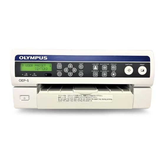
COLOR VIDEO PRINTER
OEP-5
USA: CAUTION: Federal law restricts this device to sale by or on the order of a physician.
Table of Contents
Labels and Symbols
Important Information –
Please Read Before Use
Package Contents
Installation and
Connection
Inspection Before Use
Operation
Appendix
1
2
3
4
Advertisement
Table of Contents

Related Manuals for Olympus OEP-5


Summary of Contents for Olympus OEP-5
- Page 1 Important Information – Please Read Before Use Package Contents Installation and Connection Inspection Before Use INSTRUCTIONS Operation Appendix BASIC COLOR VIDEO PRINTER OEP-5 USA: CAUTION: Federal law restricts this device to sale by or on the order of a physician.
-
Page 3: Table Of Contents
1.1 Checking the Package Contents ....8 Chapter 2 Installation and Connection 2.1 Installation of the Color Video Printer (OEP-5) ............9 2.2 Connection of the EVIS EXERA II Video System Center (CV-180) ......11 2.3 Connection to the AC Mains Power Supply ............ -
Page 4: Labels And Symbols
Labels and Symbols Safety-related labels and symbols are attached to this If labels or symbols are missing or illegible, contact instrument (OEP-5 color video printer) at the locations Olympus. shown below. Color video printer (OEP-5) Equipotential terminal Instruction manual reference mark... -
Page 5: Important Information - Please Read Before Use
High Definition Television. It is a format featuring higher image definition than the SDTV format. Intended Use The OEP-5 color video printer has been designed to be Serial Digital Interface. It is a digital interface standard used with Olympus endoscopes for recording and used in video distribution. -
Page 6: Repair And Modification
– Keep fluids away from all electrical equipment. If The following signal words are used throughout this fluids are spilled on or into this instrument, manual: immediately stop operating it and contact Olympus. – Do not prepare, inspect or use this instrument with wet hands. DANGER •... - Page 7 – Do not apply excessive force to the terminals of this instrument. • When using spray-type medical agents such as lubricate, anesthetic, or alcohol, use them away from this instrument so that the medical agents will not fall on this instrument. The medical agents possibly may come into this instrument from its ventilation grills and cause the failure.
-
Page 8: Chapter 1 Package Contents
Inspect each item for damage. If this instrument is damaged, a component is missing, or you have any questions, do not use this instrument; immediately contact Olympus. Color video printer (OEP-5) Color video printer Trial pack (100 sheets) Ink ribbon holder... -
Page 9: Chapter 2 Installation And Connection
2.1 Installation of the Color Video Printer (OEP-5) - Page 10 Place the color video printer (OEP-5) on the mobile shelf of the mobile workstation. Be sure the portion of the color video printer (OEP- 5) does not contact with the mobile workstation, etc., when you attach or remove the paper tray, or...
-
Page 11: Connection Of The Evis Exera Ii Video System Center (Cv-180)
2.2 Connection of the EVIS EXERA II Video System Center (CV-180) Attach the two black screws, provided with the remote cable (MH-995). RS-232C terminal Color video printer (OEP-5) INPUT terminals VIDEO OUT terminal BNC cable (MB-677) RGB cable (MH-984) PRINTER OUT... -
Page 12: Connection To The Ac Mains Power Supply
To connect to the AC mains power supply Moreover, if the power cord is damaged, turn OFF the power and stop using this instrument immediately and Confirm that the color video printer (OEP-5) is contact Olympus. turned OFF. – Take care to place the cord such that it is not crushed between the instrument and a wall, mobile workstation or a shelf, etc. - Page 13 Connect the power cord of the mobile workstation to a wall mains outlet. WARNING on power connection for medical Please use the following power supply cord. With connectors (plug or female) and cord types other than those indicated in this table, use the power supply cord that is approved for use in your area.
-
Page 14: Chapter 3 Inspection Before Use
Figure 3.1 If the power fails to come on If the power fails to come on, inspect according to “Chapter 7 Troubleshooting” in “INSTRUCTIONS (ADVANCED).” If power still fails to turn ON, contact Olympus. 3.1 Inspection of the Power Supply... -
Page 15: Installation Of The Color Printing Pack (Upc-55)
Take out the ink ribbon holder (see Figure 3.3). 3.2 Installation of the Color Printing Pack (UPC-55) Install the separately available color printing pack (UPC-55) on this instrument. Never use printing packs other than UPC-55. When using this instrument for the first time, the supplied trial pack can be used for an operation check. - Page 16 Set a new ink ribbon on the ink ribbon holder. Firstly, firmly secure the white gear in the ink Hold the ink ribbon right and remove the gear cover ribbon, and then the gray gear (see Figure 3.6). (see Figure 3.5). Gear (White) Gear cover Caution label...
-
Page 17: Installation Of The Print Sheets
• Do not apply excessive force to the front door. Otherwise, damage may result. Push the ink ribbon holder all the way into the color video printer (OEP-5) (see Figure 3.8). If the ink ribbon is torn in the middle Connect the torn sections with transparent plastic tape (see Figure 3.10). - Page 18 Press the “PUSH EJECT” area of the paper tray and warped print sheets. Otherwise, paper jam may take out the paper tray from the color video printer result. (OEP-5) (see Figure 3.11). Open the cover of the paper tray. If print sheets remain in the paper tray, remove them.
- Page 19 Figure 3.14 Stopper Insert the paper tray into the color video printer Figure 3.16 (OEP-5) until it clicks (see Figure 3.15). Figure 3.15 CAUTION • When attaching or detaching the paper tray, be careful not to move this instrument together.
-
Page 20: 3.3 Setup Of Connected Equipment
3.3 Setup of Connected Equipment This document, “INSTRUCTIONS (BASIC),” explains the EVIS EXERA II video system center (CV-180). Refer to the instruction manuals of the connected equipment, which must be set up as required for use with this instrument. Refer to “INSTRUCTIONS (ADVANCED)” when you use equipment other than the equipment introduced in “INSTRUCTIONS (BASIC).”... -
Page 21: Inspection Of The Lcd Panel Display
(ADVANCED)”, and take the appropriate measures. SSDAUT Auto SDI signal input detection (for SDTV input) Turn the color video printer (OEP-5) ON as HSDAUT Auto SDI signal input detection (for HDTV described in “3.1 Inspection of the Power Supply” input) on page 14. -
Page 22: Setup Of This Instrument
LCD panel ENTER button Figure 3.18 Press the “MENU” button. Depending on the connected equipment, perform setup of the color video printer (OEP-5) by following the procedures below. Table 3.4 Connecting Procedure 1 Press “v” or “V” until the LCD CV-180 panel shows “SIGNAL SETUP,”... -
Page 23: 3.6 Inspection Of The Monitor Display
3.6 Inspection of the Monitor Display The monitor displays information and messages When the color video printer (OEP-5) is connected according to the conditions of this instrument. to a video system center, display the image from the color video printer (OEP-5) on the monitor by... -
Page 24: Check The Printed Picture
Inspection of the CVP counter 3.7 Check the Printed When this instrument is connected to the following equipment, perform inspection of the CVP counter. Picture – EVIS EXERA II video system center (CV-180, CV- 160) Check whether the printed picture is desired. –... -
Page 25: Chapter 4 Operation
MRI or radio equipment). Electromagnetic Press the power switch (see Figure 4.1). radiation can interfere with the monitor display. • It is recommended to use only Olympus high- frequency electrosurgical equipment with this instrument. Non Olympus equipment can cause interference on the monitor display, or a loss of endoscopic image. -
Page 26: Control From The Connected Equipment
EVIS EXERA II video system center (CV-180) and settings of this instrument, desired operation may not Set up the color video printer (OEP-5) according to be carried out, or image data may disappear. the connected equipment as described in “3.5 Setup •... -
Page 27: In The Case Of A Paper Jam
Be sure to turn OFF the power, and disconnect the power cord and other connecting cables. Remove the ink ribbon holder and the paper tray from the color video printer (OEP-5), and then turn the color video printer (OEP-5) upside down. Power switch Figure 4.2... -
Page 28: Restart Printing
If jammed paper cannot be removed, or an error message is displayed even after taking the above procedure, stop Figure 4.6 using this instrument and contact Olympus. Remove the jammed paper slowly (see Figure 4.7). Restart Printing Even if a paper jam occurs during printing, the image of the print is held in the flash memory of this instrument so it can be reprinted. -
Page 29: Exiting From Examination
After printing is completed, turn the color video Press the PRINT button to start printing. printer (OEP-5) OFF. NOTE When you control the printer from the EVIS EXERA II video system center (CV-180), EVIS EXERA video... -
Page 30: Appendix
For further details, contact Olympus. WARNING If combinations of equipment other than those shown in the following chart are used, the full responsibility is assumed by the medical treatment facility. - Page 31 VISERA Pro Video System Center (OTV-S7Pro) VISERA Video System Center (OTV-S7V) Mobile Workstation (WM-NP1, WM-WP1) Video System (OTV-SI) Color Video Printer (OEP-5) EUS EXERA Compact Endoscopic Ultrasound Center (EU-C60) Endoscopic Ultrasound Center (EU-M30S) Remote control unit (MAJ-898) Universal Endoscopic Ultrasound Center...
-
Page 32: Operating/Transport/Storage Environment
Operating/Transport/ Specifications Storage Environment Color video printer (OEP-5) Color video printer (OEP-5) Item Specifications Power supply Rated voltage 100 – 120 V AC Operating Ambient temperature 10 – 35°C (50 to Voltage fluctuation ±10% environment 95°F) Rated frequency 50/60 Hz Relative humidity 30 –... - Page 33 Item Specifications Item Specifications Input signal HDTV signal (1080/ Year of Last digit of the year of 7101234 59.94i): production production. RGB/YPbPr video Applicable This instrument signal. standard: complies with the IEC60601-1-2: standard listed in the Y/C video signals 2001 left column.
-
Page 34: Emc Information
EMC Information This model is intended for use in the electromagnetic environments specified below. The user and the medical staff should ensure that it is used only in these environments. Magnetic emission compliance information and recommended electromagnetic environments Emission standard Compliance Guidance RF emissions... - Page 35 Cautions and recommended electromagnetic environment regarding portable and mobile RF communications equipment such as a cellular phones Immunity test IEC 60601-1-2 Compliance level Guidance test level Conducted RF 3 Vrms 3 V (V Formula for recommended separation distance IEC 61000-4-6 (150 kHz to 80 MHz) =3 according to the compliance level) Radiated RF...
-
Page 36: Fcc
Subpart B of Part 15 of FCC Rules. Declaration of Conformity Trade Name : OLYMPUS MEDICAL SYSTEMS Model : OEP-5 Responsible Party : OLYMPUS AMERICA INC. -
Page 37: Index
Remote control unit (MAJ-898) 4, 8 LCD panel display 21 Wired remote control 5 Monitor display 23 Wireless remote control 5 Power supply 14 Installation of the OEP-5 Cautions 9 On the mobile workstation (WM- SDTV 5 NP1, WM-WP1) 10 Setup... - Page 38 Index...
- Page 39 ©2011 OLYMPUS MEDICAL SYSTEMS CORP. All rights reserved. No part of this publication may be reproduced or distributed without the express written permission of OLYMPUS MEDICAL SYSTEMS CORP. OLYMPUS is a registered trademark of OLYMPUS CORPORATION. The product names, logos and company names in this instruction manual are generally trademarks or registered trademarks of each company.
- Page 40 GT7518 02 Printed in Japan 4-258-624-31(1)
Need help?
Do you have a question about the OEP-5 and is the answer not in the manual?
Questions and answers
How do I print pictures from the memory