Table of Contents
Advertisement
INSTRUCTIONS
ADVANCED
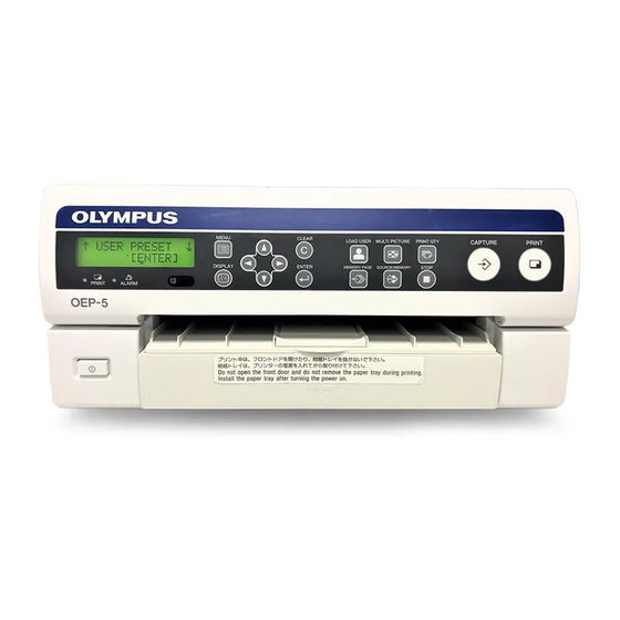
COLOR VIDEO PRINTER
OEP-5
USA: CAUTION: Federal law restricts this device to sale by or on the order of a physician.
Table of Contents
Labels and Symbols
Important Information –
Please Read Before Use
Instrument Nomenclature
and Functions
Installation and
Connection
Inspection Before Use
Operation
System Setup
Care, Storage and
Disposal
Troubleshooting
Appendix
1
2
3
4
5
6
7
Advertisement
Table of Contents

Related Manuals for Olympus OEP-5


Summary of Contents for Olympus OEP-5
- Page 1 Functions Installation and Connection Inspection Before Use INSTRUCTIONS Operation System Setup ADVANCED Care, Storage and Disposal COLOR VIDEO PRINTER OEP-5 Troubleshooting Appendix USA: CAUTION: Federal law restricts this device to sale by or on the order of a physician.
-
Page 3: Table Of Contents
2.11Connection of the Medical Control Unit For Table of Contents Endosurgery (UCES-3) ........27 2.12Connection of the Control Unit For Endosurgery (UCES-2) ........28 2.13Preparation of the Remote Control Unit Labels and Symbols (MAJ-898) (Optional) ........29 2.14When no Mobile Workstation is Used ..30 Important Information –... - Page 4 Chapter 6 Care, Storage and Disposal 6.1 Care ............... 72 6.2 Displacement ..........72 6.3 Storage ............73 6.4 Disposal ............73 Chapter 7 Troubleshooting 7.1 Troubleshooting Guide ........ 74 Countermeasures Against Messages ....79 7.2 Sending this Instrument for Repair .... 82 Appendix Index ..............
-
Page 5: Labels And Symbols
Labels and Symbols Safety-related labels and symbols are attached to this If labels or symbols are missing or illegible, contact instrument (OEP-5 color video printer) at the locations Olympus. shown below. Color video printer (OEP-5) Equipotential terminal Instruction manual reference mark... -
Page 6: Important Information - Please Read Before Use
Intended Use – Increase the separation between the equipment and receiver. The OEP-5 color video printer has been designed to be – Connect the equipment into an outlet on a circuit used with Olympus endoscopes for recording and different from that to which the receiver is connected. -
Page 7: Instrument Compatibility
Isolation transformer instrument is compatible with the ancillary equipment The isolation transformer is a safety device that is used being used. Using incompatible equipment can result in to isolate non insulated equipment with potentially high patient or operator injury and/or equipment damage. It leakage currents to decrease the possibility of electric may also impair the functionality of the instrument. -
Page 8: Repair And Modification
“Chapter 7 Troubleshooting” on page 74. If the problem cannot be resolved using the instrument is not explosion-proof. information in Chapter 7, contact Olympus. WARNING • Be sure to turn this instrument OFF and unplug the... - Page 9 • Electromagnetic interference may occur to this instrument near equipment marked with the following symbol or other portable and mobile radio telecommunications equipment such as cellular phones. If radio interference occurs, mitigation measures may be necessary, such as reorienting or relocating this instrument or shielding the location.
-
Page 10: Chapter 1 Instrument Nomenclature And Functions
Chapter 1 Instrument Nomenclature and Functions Remote Control Unit (MAJ-898) (optional) 1.1 Symbols Move Up Move Down Front Panel Move Left Move Right Power ON/OFF Capture Backspace Capture Print Alarm Print Clear Menu Clear Memory Page Source/Memory Display Enter Move Up Move Down Move Left Move Right... -
Page 11: Front Panel
1.2 Front Panel A ! Power switch F Cursor (v/V/b/B) keys Press to turn this instrument ON, and press again to When the normal image is displayed : Move turn it OFF. the pointer in the arrow direction. When the menu is displayed : Move the cursor B Front door in the arrow direction. - Page 12 MULTI PICTURE button In the normal display, press to select the number of images to be stored in a memory page for multi- picture printing. After the first press, the current setup is displayed for a few seconds. Further presses vary the setup in the cycle of 1, 2, 3, 4, 1,…. STOP button Press to stop continuation printing.
-
Page 13: Rear Panel
1.3 Rear Panel A Power inlet H REMOTE 3 terminal Connect the power cord for AC power supply. This terminal is for future expansion. Not used. B Equipotential terminal I OUTPUT (RGB video output) terminals For safety, connect this terminal to the equipotential Output the RGB video signals to connected bus bar of the hospital. -
Page 14: Ancillary Equipment
1.4 Ancillary Equipment Paper tray Cover Stopper Caution label Handling cautions are described here. View inside the cover Positioning mark Ink ribbon holder Caution label Handling cautions are described here. Trial pack Print sheets and ink ribbon for checking the operation of this instrument. -
Page 15: Remote Control Unit (Maj-898) (Optional)
1.5 Remote Control Unit (MAJ-898) (Optional) A MULTI PICTURE key F DISPLAY key Same function as the “MULTI PICTURE” button Same function as the “DISPLAY” button on the on the front panel. front panel. B MENU key BACK SPACE key Same function as the “MENU”... - Page 16 M EXEC key Same function as the “ENTER” button on the front panel. N Arrow keys Same function as the cursor keys on the front panel. O R REMAIN key Press to display the ribbon remaining information. Each subsequent press of this key toggles between ON or OFF.
-
Page 17: Chapter 2 Installation And Connection
Chapter 2 Installation and Connection 2.1 Before Installation and Connection This document, “INSTRUCTIONS (ADVANCED),” explains equipment other than that described in “INSTRUCTIONS (BASIC).” Prepare this instrument and compatible equipment, referring to the instruction manuals of each system component. Install and connect the equipment as follows: WARNING Review “INSTRUCTIONS (BASIC)”... -
Page 18: Connection Of The Evis Exera Video System Center (Cv-160)
To RGB, Y/C, or VIDEO input terminal of a monitor Attach the two black screws, provided with the To remote terminal of a monitor remote cable (MH-995). VIDEO OUT Color video printer (OEP-5) terminal RS-232C terminal INPUT terminals RGB cable (MH-984) BNC cable (MB-677) -
Page 19: Connection Of The Visera Pro Video System Center (Otv-S7Pro)
Attach the two black screws, provided with the To RGB, Y/C, or VIDEO input remote cable (MH-995). terminal of a monitor RS-232C terminal Color video printer (OEP-5) INPUT terminals VIDEO OUT terminal Monitor Cable BNC cable (MB-677) RGB cable (MH-984) -
Page 20: Connection Of The Visera Video System Center (Otv-S7V)
2.4 Connection of the VISERA Video System Center (OTV-S7V) To a monitor Color video printer (OEP-5) To Y/C input terminal of a monitor INPUT terminals REMOTE 2 VIDEO IN S VIDEO IN S VIDEO terminal terminal terminal terminal OEP cable (MH-987) -
Page 21: Connection Of The Video System (Otv-Si)
2.5 Connection of the Video System (OTV-SI) To VIDEO input terminal of a monitor To Y/C input terminal of a monitor REMOTE 2 terminal Color video printer (OEP-5) S VIDEO OUT terminal S VIDEO IN terminal Y/C cable Y/C cable (MH-985) -
Page 22: Connection Of The Universal Endoscopic Ultrasound Center (Eu-Me1)
2.6 Connection of the Universal Endoscopic Ultrasound Center (EU-ME1) To RGB, Y/C, or VIDEO input terminal of a monitor To VIDEO input terminal REMOTE 2 terminal of a monitor Color video printer (OEP-5) INPUT terminals VIDEO OUT terminal BNC cable RGB cable (MAJ-686) -
Page 23: Connection Of The Endoscopic Ultrasound Center (Eu-M30S)
2.7 Connection of the Endoscopic Ultrasound Center (EU-M30S) To RGB, Y/C, or VIDEO input terminal of a monitor Color video printer (OEP-5) S-VIDEO IN terminal Y/C cable (MH-985) Endoscopic Ultrasound Center (EU-M30S) RGB OUT terminal Y/C OUT terminal RGB cable Figure 2.6... -
Page 24: Connection Of The Eus Exera Endoscopic Ultrasound Center (Eu-M60)
2.8 Connection of the EUS EXERA Endoscopic Ultrasound Center (EU-M60) To RGB, Y/C, or VIDEO input terminal of a monitor To VIDEO input terminal of RS-232C terminal a monitor Color Video Printer (OEP-5) VIDEO OUT INPUT terminal terminals White Blue... -
Page 25: Connection Of The Eus Exera Compact Endoscopic Ultrasound Center (Eu-C60)
To VIDEO input terminal of a monitor To Y/C input terminal REMOTE 2 of a monitor terminal VIDEO IN terminal Color Video Printer (OEP-5) S VIDEO OUT terminal Y/C cable BNC cable (MB-677) Remote cable (MH-907) PRINTER REMOTE terminal VIDEO 2 OUT terminal... -
Page 26: Connection Of The Image Management Hub (Imh-20, Imh-10)
2.10 Connection of the Image Management Hub (IMH- 20, IMH-10) RS-232C terminal Color video printer (OEP-5) SDI video input terminal SDI cable (MAJ-1951) Image Management Hub (IMH-20, IMH-10) SDI video output terminal REMOTE1 Made by Sanwa Supply terminal Gender changer (D9S-FF) Communication cable (MAJ-202) Figure 2.9... -
Page 27: Connection Of The Medical Control Unit For Endosurgery (Uces-3)
2.11 Connection of the Medical Control Unit For Endosurgery (UCES-3) VTR remote cable (MAJ-438) REMOTE2 terminal Color video printer (OEP-5) REMOTE1 terminal Medical Control Unit For Endosurgery (UCES-3) Figure 2.10 NOTE To connect to the Medical Control Unit For Endosurgery... -
Page 28: Connection Of The Control Unit For Endosurgery (Uces-2)
2.12 Connection of the Control Unit For Endosurgery (UCES-2) Communication cable (MAJ-202) RS-232C terminal Color video printer (OEP-5) S VIDEO IN terminal Y/C cable (MH-985) OUTPUT A terminal (RECORDER) Control Unit For Endosurgery (UCES-2) System terminal Figure 2.11 NOTE To connect to the Control Unit For Endosurgery (UCES- 2), also refer to the instruction manual supplied with the Control Unit For Endosurgery (UCES-2). -
Page 29: Preparation Of The Remote Control Unit (Maj-898) (Optional)
Connect a remote cable between the REMOTE 1 Danger of explosion if battery is incorrectly replaced. terminal of the color video printer (OEP-5) and the Replace only with the same or equivalent type cable connector of the remote control unit (MAJ- recommended by the manufacturer. -
Page 30: When No Mobile Workstation Is Used
Confirm that the color video printer (OEP-5) is turned OFF. Connect the power cord of the color video printer (OEP-5) to its AC mains power outlet first, then to a wall mains outlet. The following ancillary equipment can be connected directly to wall mains outlets (see Figure 2.13). - Page 31 EUS EXERA compact endoscopic ultrasound center (EU-C60) High definition LCD monitor (OEV261H, OEV191H) LCD monitor (OEV191) Color video printer (OEP-5) Image Management Hub (IMH-20, IMH-10) Medical control unit for endosurgery (UCES-3) Control unit for endosurgery (UCES-2) Connection via an isolation transformer:...
-
Page 32: Chapter 3 Inspection Before Use
Chapter 3 Inspection Before Use This document, “INSTRUCTIONS (ADVANCED),” explains equipment other than described in “INSTRUCTIONS (BASIC).” Refer to the instruction manuals of the connected equipment, which must be set up as required for use with this instrument. Be sure to refer to “Chapter 3 Inspection Before Use” in “INSTRUCTIONS (BASIC),”... - Page 33 Table 3.1 Connected Instruction Manual Setup Item Setup Note equipment references OTV-S7Pro “9.2 System setup” “Type” “OEP4” Select the printer type. Be sure to set “Type” “Printer” to “OEP4” when using this instrument. “Qty. “N”” “4” – “ 9” Select the print quantity when the “Print quantity indicator”...
- Page 34 “4.2 Recording setting “REMOTE1” “OEP-5” Select the model of printer to connect. Be sure (User settings)” to set this item to “OEP-5” when using this instrument. “Layout” “1 image (1 × 1)” Select the number of multi-pictures to be “2 images (1 × 2)”...
-
Page 35: Setup Of This Instrument
3 Press “v” or “V” until the format Depending on the connected equipment, perform of the video signal being input appears below “INPUT SEL,” press setup of the color video printer (OEP-5) by the “ENTER” button. following the procedures below. VIDEO : Input the signal in composite signal formats. - Page 36 Table 3.2 Connected Procedure Instrument EU-M60 You can use these devices at the factory settings. 1 Press “v” or “V” until the LCD EU-C60 panel shows “SIGNAL SETUP,” and press the “ENTER” button. 2 When “INPUT SETUP” appears, press “v” or “V” to display “INPUT SEL,”...
-
Page 37: Chapter 4 Operation
• Do not set the number of multi-picture to “8” or “16” Set up the color video printer (OEP-5) as described from the EVIS EXERA video system center (CV-160) in “3.2 Setup of this Instrument” on page 35. -
Page 38: Control From The Front Panel
Connected Description in instructions 4.2 Control From the Instrument EU-M30S Section 6.9, “Recording” “Image Front Panel recording using OEP” EU-M60 Section 6.13, “Operation of ancillary equipment (printer, VTR, etc.)” NOTE “Image recording using the color video printer” To check the setup values on the monitor, connect the video output signal from this instrument to the monitor EU-C60 Section 6.8, “Recording”... -
Page 39: Selecting The User Setup
The monitor and LCD panel display the current Selecting the User Setup setup for a few seconds. On the monitor, the user Select the user setup registered in “Save” in USER number currently selected is displayed in green (see PRESET menu. Figure 4.3). -
Page 40: Setting The Print Quantity
Setting the Print Quantity NOTE The number of printing the same picture can be set up. The print quantity can also be controlled in a menu. The setup made using the above procedure is also applied to Press the “PRINT QTY” button on the front panel the setup using the menu. - Page 41 The monitor and LCD panel display correspond Table 4.2 with the number of multi-pictures as shown in Figure 4.7 and Table 4.2. The printed picture Monitor Screen LCD Panel Number of Multi- becomes as shown in Figure 4.8. The memory Display Display Picture Images...
-
Page 42: Capturing The Image
Confirm that the Source/Memory display shows Capturing the Image “M.” If not, press the “SOURCE/MEMORY” Images to be printed on print sheets can be captured in button until “M” is displayed. this instrument as described below. “M” indicates that a memory image is being displayed (see Figure 4.11). -
Page 43: Selecting The Memory Page
“CAPTURE” button to store it in the memory of • If you turn OFF this instrument while the “PRINT” color video printer (OEP-5). lamp is lit, the ink ribbon quantity displayed on the remaining ink ribbon display on the LCD display and/... -
Page 44: Stop Printing
Press the “MEMORY PAGE” button repeatedly Press the “STOP” button (see Figure 4.15). until the memory page to be used is displayed (see Printing stops after completing printing of the Figure 4.13 and Figure 4.14). current sheet. Each press of the “MEMORY PAGE” button switches the memory page. -
Page 45: Control From The Remote Control Unit (Maj-898) (Optional)
Table 4.4 4.3 Control From the Remote control unit Front panel switches Remote Control Unit keys INPUT SELECT key No corresponding switch. This (MAJ-898) function should be selected from a menu. (Optional) R REMAIN key No corresponding switch. This function should be selected from a The optional remote control unit (MAJ-898) can be used menu. -
Page 46: Chapter 5 System Setup
Chapter 5 System Setup 5.1 Items That can be Set on Menus The system setups of this instrument can be modified as desired by the user or according to the operations applied from the factory default. This instrument may malfunction if the system setups are made incorrectly. Moreover, in the case of an item that cannot be set up, its setting value will be displayed as “__”... - Page 47 STORE MODE “OEP-4 MODE” Set a mode in which image and setting data is “OEP-4 MODE” “OEP-5 MODE” saved or loaded when a paper jam occurs. “OFF” STORE IMAGE “STORE” Store, load or clear image and setting data “RESTORE”...
- Page 48 Set whether white frames are placed in the “ON” multi-picture images. CAPTION 80 characters Input a comment (caption) at the bottom of “OLYMPUS COLOR the print picture. VIDEO PRINTER” PICTURE LOAD COLOR “1” “2” “3” Load the saved color setup.
- Page 49 Table 5.1 Menu Item Setting values Details Factory default PICTURE WINDOW “SD” “SD-SDI” “4 : 3” For SDTV, display the input video signal of Depending on “INPUT SETUP - “5 : 4” “16 : 9” the image capture. SEL” in “INPUT WINDOW “16 : 10”...
- Page 50 Table 5.1 Menu Item Setting values Details Factory default ZOOM H START(NR) “0” to “1000” This function is for future expansion. Not “240” SETUP - ZM used. ADJ(L) V START(NR) “0” to “200” This function is for future expansion. Not “0”...
-
Page 51: Menu Tree
5.2 Menu Tree MENU Edit (page 53) USER PRESET (page 53) Color tone adjustment (page 54) PRINTER SETUP (page 55) PRINTER SETUP (page 55) INPUT SETUP (page 60) SYSTEM SETUP (page 56) SIGNAL SETUP OUTPUT SETUP (page 62) FUNCTION SETUP (page 57) HDTV SETUP (page 63) COLOR BALANCE (page 59) Figure 5.1... - Page 52 CAPTION (page 65) LAYOUT SETUP (page 64) PICTURE SETUP COLOR ADJUST (page 66) WINDOW SETUP (page 68) ZOOM MODE (page 69) ZOOM SETUP ZM ADJ(S) (page 70) ZM ADJ(L) (page 70) Figure 5.1 5.2 Menu Tree...
-
Page 53: Setup Of The "User Preset" Menu
Setting “Save” 5.3 Setup of the “USER This item is used to save all of the current system setups in all menus. PRESET” Menu Press “v” or “V” to select “Save,” and press the “ENTER” button. This menu is used to store/select the setups of this instrument or edit the user name for every user. -
Page 54: Setup Of The "Color Tone Adjustment" Menu
To switch the uppercase and lowercase 5.4 Setup of the “Color letters 1 Press “v,” “V,” “b” or “B” to move the cursor tone adjustment” on “SHIFT.” 2 Press the “ENTER” button. Menu When uppercase letters are displayed, they are switched to lowercase letters. -
Page 55: Setup Of The "Printer Setup" Menu
SOFT : The picture to be printed contains a large 5.5 Setup of the white area. “PRINTER SETUP” NORMAL : Printing an ordinary picture. HARD : The picture to be printed contains a large Menu black area. This menu is used in the overall setups of this Setting “HD GAMMA”... -
Page 56: Setup Of The "System Setup" Menu
Setting “BAUDRATE” 5.6 Setup of the This item is used to set the RS-232C communication rate. “4800” is selected when this instrument is “SYSTEM SETUP” connected to the video system center or the endoscopic ultrasound center. Menu Press “v” or “V” to select “BAUDRATE,” and This item is used in detailed system-related setups of press the “ENTER”... -
Page 57: Setup Of The "Function Setup" Menu
Table 5.3 5.7 Setup of the Setting Function “FUNCTION CAPTURE Captures an image. SETUP” Menu PRINT Prints the picture. C&PRINT Captures and prints a picture. This menu is used to set details of the functions of this CYCLIC-C Stores images cyclically in the memory, instrument. - Page 58 4.3 “In the Case of a Paper Jam” of “INSTRUCTIONS (BASIC).” OEP-5 MODE : Sets not to display a message when the power of this instrument is turned on after a paper jam is cleared. (The saved data can be loaded.)
-
Page 59: Setup Of The "Color Balance" Menu
Press “v” or “V” to select “BAL X,” and press the 5.8 Setup of the “ENTER” button. “COLOR Press “v” or “V” to select between “1” to “99,” and press the “ENTER” button. BALANCE” Menu Press “v” or “V” to select “BAL Y,” and press the This menu is used to adjust the color balance in the “ENTER”... -
Page 60: Setup Of The "Input Setup" Menu
Color tones in test printed pictures 5.9 Setup of the “INPUT SETUP” Menu Yellow-greenish Yellowish Amberish This menu is used to set up the input signal. When the setup of the “INPUT SEL,” “SD/HD SEL,” “SD FORMAT,” or “SD SYNC(IN)” is changed, the Greenish Standard Reddish... - Page 61 This setup is valid only when “COMPONENT” or EXT : The sync separation type video signals “SDI” is selected in the “Setting “INPUT SEL”” menu (see on page 60). Setting “HUE” In addition, the HDTV image and the SDTV image This item is used to adjust the hue of the printed picture cannot be printed together on one print sheet.
-
Page 62: Setup Of The "Output Setup" Menu
Press “v” or “V” to select either “OFF” or “ON,” 5.10 Setup of the and press the “ENTER” button. OFF : Remaining ink ribbon information is not “OUTPUT SETUP” displayed. Menu ON : Remaining ink ribbon information is displayed. This menu is used to set up the output signal of this Setting “SOURCE”... -
Page 63: Setup Of The "Hdtv Setup" Menu
Setting “OUTPUT SIG” 5.11 Setup of the “HDTV This item is used to select the format of the output video signal from this instrument when the HDTV video SETUP” Menu signal is input to this instrument. Press “v” or “V” to select “OUTPUT SIG,” and This menu is used in the basic setups of this instrument press the “ENTER”... -
Page 64: Setup Of The "Layout Setup" Menu
Setting “HD GAMMA” 5.12 Setup of the See “Setting “HD GAMMA”” on page 55. “LAYOUT SETUP” Setting “AUTO PRINT” This item is used to select the operation to be initiated Menu when the input video signal to this instrument is switched from the HDTV signal to the SDTV signal or vice versa. - Page 65 Press “v” or “V” to select either “ON” or “OFF,” NOTE and press the “ENTER” button. When this instrument is controlled from the EVIS EXERA Video System Center (CV-160) , enter captions from the connected equipment. Entering from this instrument when the EVIS EXERA Video System Center (CV-160) is connected may fail to enter the desired caption.
-
Page 66: Setup Of The "Color Adjust" Menu
To insert a character in the middle of a 5.13 Setup of the comment 1 Press “v,” “V,” “b” or “B” to move the cursor “COLOR ADJUST” on “INS.” 2 Press the “ENTER” button. Now characters can Menu be inserted by repeating steps 3 and 4. To input a space This menu is used for adjustments to color and 1 Press “v,”... - Page 67 Setting “CYN-RED,” “MAG-GRN,” “YEL-BLU” Setting “SD SHARPNESS” This item is used to adjust the color tone in 15 steps in This item is used to set the level of the edge the printed picture and the image on the monitor. enhancement in the printed picture when an SDTV The color tone in the printed picture and the image on signal is input to this instrument.
-
Page 68: Setup Of The "Window Setup" Menu
To display “WINDOW” 5.14 Setup of the This item is used to display the input video signal of a captured image as STDV signal, or aspect ratios for “WINDOW SETUP” HDTV signal. Menu Setting “H START,” “V START,” “H WIDTH,” “V WIDTH”... -
Page 69: Setup Of The "Zoom Mode" Menu
Press “v” or “V” to select either “OFF” or “ON,” 5.15 Setup of the “ZOOM and press the “ENTER” button (see Figure 5.20). MODE” Menu This item is used to set the print layout when the HDTV signal is input to this instrument and 4 multi-picture images are to be printed. -
Page 70: Setup Of The "Zm Adj(S)" "Zm Adj(L)" Menu
Press “v” or “V” to select from among “OFF,” 5.16 Setup of the “ZM “PART,” “ALL” and “REMOTE,” and press the “ENTER” button (see Figure 5.22). ADJ(S)” “ZM ZOOM PART “OFF” ZOOM PART “PART” ADJ(L)” Menu When an HDTV signal is input to this instrument and 4 multi-picture images are to be printed, this menu can be used to zoom into one or all of the images by setting the image capturing range. - Page 71 Press “v” or “V” to select the values as described in Table 5.7, and press the “ENTER” button. Table 5.7 Setting item Setting value H START (RS) 240 to 1000 V START (RS) 0 to 200 H WIDTH 600 to 1400 V WIDTH 600 to 1400 Repeat steps 1 and 2 to set the image capturing...
-
Page 72: Chapter 6 Care, Storage And Disposal
Chapter 6 Care, Storage and Disposal Make sure that the color video printer (OEP-5) is 6.1 Care completely dry before use. After using this instrument, immediately perform the following cleaning procedure. If cleaning is delayed, 6.2 Displacement residual organic debris will begin to solidify, and it may be difficult to effectively clean this instrument. -
Page 73: Storage
For information on the storage of the color printing pack (UPC-55), refer to the instruction manual for the color printing pack (UPC-55). Turn the color video printer (OEP-5) OFF and disconnect the power cord. Disconnect all cables connected to the color video printer (OEP-5). -
Page 74: Chapter 7 Troubleshooting
As repair performed by persons who are not qualified by Olympus could cause patient or operator injury and/or equipment damage, be sure to contact Olympus for repair as described in “7.2 Sending this Instrument for Repair”. Irregularity... - Page 75 Irregularity Possible cause Solution The buzzer keeps A trouble occurred inside this instrument. Turn this instrument OFF, then ON again after a while. sounding. No image is displayed on The switches on the rear and/or front of the Set the switches properly as described in the instruction the monitor.
- Page 76 Irregularity Possible cause Solution Remote control from the The remote cable is connected improperly. Connect it properly as described in “Chapter 2 connected equipment is not Installation and Connection” in “INSTRUCTIONS available. (BASIC)” or “Chapter 2 Installation and Connection” on page 17 in “INSTRUCTIONS (ADVANCED).”...
- Page 77 Irregularity Possible cause Solution The number displayed on The communication problem has occurred Turn this instrument OFF, then ON again. the “CVP counter” does not between this instrument and connected Turn the connected equipment OFF, then ON again. increase even if an image equipment.
- Page 78 (ADVANCED).” A line goes into a print The thermal head has reached the end of its Contact Olympus. The thermal head can be exchanged. picture. service life. There is rattling sound There are only a few print sheets in the paper This is normal for this product, and is not a malfunction.
-
Page 79: Countermeasures Against Messages
“3.2 Installation of the Color Printing Pack (UPC-55)” in “INSTRUCTIONS (BASIC).” If the ink ribbon is not cut, contact Olympus. CHECK PAPER: LOAD nn CHECK PAPER nn LOAD Paper jam inside this instrument. Removed the jammed paper as described in “4.3 In the Case of a... - Page 80 Message Possible cause Solution Monitor LCD panel MECHA TROUBLE: MECHA TROUBLE nn Paper jam inside this instrument. Removed the jammed paper as PROCESS nn PROCESS described in “4.3 In the Case of a Paper Jam” in “INSTRUCTIONS (BASIC).” A trouble other than paper jam Turn this instrument OFF, then occurred inside this instrument.
- Page 81 Clock Low Battery CLOCK LOW BATTERY Contact Olympus. PLZ contact service center Read error in the Flash Memory FLASH MEMORY READ ERROR Write error in the Flash Memory FLASH MEMORY WRITE ERROR The Flash Memory is protected.
-
Page 82: Sending This Instrument For Repair
Also include a repair purchase order. WARNING Olympus is not liable for any injury or damage that occurs as a result of repairs attempted by non Olympus personnel. 7.2 Sending this Instrument for Repair... -
Page 83: Index
Appendix Equipotential terminal 5, 10, 13 PRINTER SETUP menu 55 Index EUS EXERA compact endoscopic SYSTEM SETUP menu 56 ultrasound center 30, 31 Tree 51 EUS EXERA endoscopic ultrasound USER PRESET menu 53 center 30, 31 WINDOW SETUP menu 68 EVIS EXERA video system center ZM ADJ(L) menu 70 ALARM lamp 12... - Page 84 Rear panel 10, 13 Wall mains outlet 6, 31 REMOTE 1 terminal 13 Wired remote control 7, 29 REMOTE 2 terminal 13, 20, 21, 22, Wireless remote control 7, 29 REMOTE 3 terminal 13 Remote cable 16, 29 Remote Control Unit (MAJ-898) 5, 10, 15, 29, 45 Remote sensor 12 RS-232C terminal 13, 19, 24, 26...
- Page 85 Index...
- Page 86 Index...
- Page 87 ©2011 OLYMPUS MEDICAL SYSTEMS CORP. All rights reserved. No part of this publication may be reproduced or distributed without the express written permission of OLYMPUS MEDICAL SYSTEMS CORP. OLYMPUS is a registered trademark of OLYMPUS CORPORATION. The product names, logos and company names in this instruction manual are generally trademarks or registered trademarks of each company.
- Page 88 GT7519 02 Printed in Japan 4-258-625-31(1)
Need help?
Do you have a question about the OEP-5 and is the answer not in the manual?
Questions and answers
E407 ERROR CODE
What does it mean when you get an error OEP-5 ERR E407. Processing failed?