Table of Contents
Advertisement
Quick Links
Installation, Operating, Servicing and
Conversion Instructions
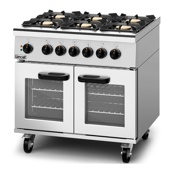
Phoenix Gas Open Top Electric Oven Range
PHDR01
Please make a note of your product details for
future reference:
Date Purchased: _______________________
Model Number: ________________________
Serial Number: ________________________
Dealer: ______________________________
IS744 ECN 4665
Page 1 of 1
Advertisement
Table of Contents

Subscribe to Our Youtube Channel
Related Manuals for Lincat Phoenix Series


Summary of Contents for Lincat Phoenix Series
- Page 1 Installation, Operating, Servicing and Conversion Instructions Phoenix Gas Open Top Electric Oven Range PHDR01 Please make a note of your product details for future reference: Date Purchased: _______________________ Model Number: ________________________ Serial Number: ________________________ Dealer: ______________________________ IS744 ECN 4665 Page 1 of 1...
-
Page 2: Table Of Contents
WARNING! This symbol is used whenever there is a risk of personal injury. CAUTION! This symbol is used whenever there is a risk of damaging your Lincat product. NOTE: This symbol is used to provide additional information, hints and tips. -
Page 3: Warnings And Precautions
WARNINGS AND PRECAUTIONS This appliance must be installed, commissioned, serviced and converted by a qualified person in accordance with national and local regulations in force in the country of installation. Strip plastic coating and clean the appliance before use. During operation parts may become hot - avoid accidental contact. Parts protected by the manufacturer shall not be adjusted by the user. -
Page 4: Technical Data
TECHNICAL DATA Model PHDR01 Dimensions Height (mm) Width (mm) Depth (mm) Weight (kg) Hob Cooking Surface w x d (mm) 900 x 600 Useable Oven Capacity w x d x h (mm) 715 x 530 x 400 Oven Shelf w x d (mm) 710 x 512 Connection and Operating Pressures ¾”... -
Page 5: Checklist Of Enclosures
Pan Supports Oven Shelves SERIAL NUMBER Each appliance manufactured at Lincat has a unique identifying number found in NOTE the top right hand corner of the data plate attached at the rear of the appliance. Please record that number in the space provided should it be required for future reference. -
Page 6: Access, Sitting, Gas Supply, Supply Pressure
ACCESS THROUGH NARROW DOOR WAYS The overall depth of the appliance (including door handles) is 825mm. This can be reduced further to an overall depth of 750mm by the following steps. 1. Remove the pan supports, burner caps and oven shelves. 2. - Page 7 GAS SUPPLY AND CONNECTION The gas inlet connection is at the rear of the appliance. The pipe work should be of adequate size but not smaller than the gas inlet connection at the rear of the appliance, i.e. Rp ¾” BSP. The gas supply tubing or hose shall comply with national requirements in force and shall be periodically inspected and replaced as necessary.
-
Page 8: Operating Instructions
OPERATING INSTRUCTIONS APPLIANCE USE This appliance is only for professional use and should only be used by qualified personnel. Ensure that the person responsible understands how to light, safely operate, clean and shut down the appliance and is made aware of the position and operation of the gas isolating cock in the event of an emergency. - Page 9 OVEN TEMPERATURES The temperatures on the thermostat knob are a guide and generally reflect the temperature at the centre of the oven. The temperatures in the oven will vary slightly from top to bottom. It may be necessary to periodically rotate product being cooked to ensure even cooking.
-
Page 10: Cleaning
CLEANING Your Lincat product has a manufacturer’s warranty. This requires you to maintain and care for your product and follow maintenance instructions. If you fail to maintain your unit or damage components Lincat may charge you for warranty repair. Please check the website for terms and conditions. -
Page 11: Servicing And Maintenance
SERVICING AND MAINTENANCE All servicing, maintenance and component replacement on this appliance should be carried out by one of our recommended service engineers. The electrical supply must be isolated before removing any exterior panels SERVICE ACCESS To gain access gas control valves remove the control knobs (A) by pulling free from spindles. -
Page 12: Component Replacement
COMPONENT REPLACEMENT Hob Thermocouple Replacement Remove the fascia panel and control knobs as per Fig 4 Loosen the thermocouple tail nut (D) and withdraw the thermocouple from the valve Fig 6 Access to the front burners is from the front behind the fascia panel Access to the rear burners is from the rear by removing air intake covers Loosen the nut of the thermocouple head... - Page 13 Oven Thermostat and Fan Switch Replacement Remove the fascia panel and control knobs as per Fig 4 Remove the two screws F to free the fan switch and oven thermostat from the fascia panel Fig 8 To free the thermostat G from the fan switch H, pull the two components apart.
- Page 14 Oven Thermostat Replacement Remove the rear access panel J. Uncoil the thermostat capillary from Fig 9 and feed the thermostat bulb through the upper cavity. Feed the bulb through the grommets in the upper cavity through to the lower section of the appliance. Feed the thermostat bulb through the insulation and rear oven cavity panel into the thermostat bracket within the oven...
- Page 15 Remove the element retaining screws L and withdraw the element M from the cavity Fit the replacement element and secure fully. Refit the fan guard and reconnect the wires to the element terminals Replace the rear access panels Reinstall the oven shelves Reinstate power and perform PAT test Fig 12 Replacing the Fans and Motors...
- Page 16 The fan assembly comprises of 4 components To remove the motor from the appliance follow steps in Fig 13 & Fig 14 The motor can be removed from the fixing plate R, by removing the retaining screws Fig 15 Other parts as in Fig 16 can be replaced if necessary.
- Page 17 Door Replacement Open both oven doors and undo the two lower hinge fixing screws Pull door away together with lower hinge and lower the door assembly free of the top hinge pin taking care not to lose the upper door bush Replace and fit in reverse order.
-
Page 18: Conversion
CONVERSION Conversion of Gas Type – Injector Changes Model Inlet Pressure Injector Mark Part No. 1.10 JE275 x 6 0.74 JE250 x 1 20 mbar 1.86 JE05 x 6 2.30 JE28 x 1 PHDR01 0.74 JE250 x 6 0.51 JE251 x 1 37 mbar 1.20... -
Page 19: Fault Finding
FAULT FINDING Burner/s will not light or stay lit Is there gas at the burner? Check injector for blockages Are thermocouple connections loose? Tighten connections Is the thermocouple voltage less than 15mV? Replace thermocouple Is the valve damaged? Replace valve Recheck system Oven fails to heat Is the green neon lit... -
Page 20: Spare Parts List
SPARE PARTS LIST Part number Part description BU50 BURNER BODY BU51 BURNER CAP BU52 VENTURI BU53 INJECTOR HOUSING BU54 BURNER GASKET BU55 UPPER DOOR BUSH BU72 LOWER DOOR BUSH CA143 125MM CASTOR OPUS SWIVEL BRAKED CA145 125MM CASTOR OPUS SWIVEL UNBRAKED CO113 COPPER WASHER CO215... - Page 21 Part Number Description OA8902 Splashback/Shelf IS744 ECN 4665 Page 21 of 21...
-
Page 22: Appliance Dimensions
APPLIANCE DIMENSIONS G denotes gas inlet connection IS744 ECN 4665 Page 22 of 22... -
Page 23: Service Information And Guarantee
Gas Appliance Regulations 2016/426. GUARANTEE This unit carries a comprehensive UK mainland warranty. The guarantee is in addition to, and does not diminish your statutory or legal rights. Contact Lincat for terms and conditions The guarantee does not cover: ... - Page 24 IS744 ECN 4665 Page 24 of 24...
Need help?
Do you have a question about the Phoenix Series and is the answer not in the manual?
Questions and answers