Sign In
Upload
Download
Table of Contents
Contents
Add to my manuals
Delete from my manuals
Share
URL of this page:
HTML Link:
Bookmark this page
Add
Manual will be automatically added to "My Manuals"
Print this page
×
Bookmark added
×
Added to my manuals
Manuals
Brands
Lincat Manuals
Ranges
SLR6
Installation, operating, servicing and conversion instructions
Lincat SLR6 Installation, Operating, Servicing And Conversion Instructions
Hide thumbs
Also See for SLR6
:
Installation, user & servicing instructions
(13 pages)
1
2
Table Of Contents
3
4
5
6
7
8
9
10
11
12
13
14
15
16
17
18
19
20
page
of
20
Go
/
20
Contents
Table of Contents
Bookmarks
Table of Contents
Customer Information
Important Information
Table of Contents
Warnings and Precautions
Technical Data
Commissioning
Check List of Enclosures
Serial Number
Technical Data
Installation
User
Servicing
Conversion
Spare Parts List
Fault Finding
Accessories
Service Information
Guarantee
Advertisement
Quick Links
1
Installation
2
Servicing
3
Spare Parts List
Download this manual
Installation, Operating, Servicing and
Conversion Instructions
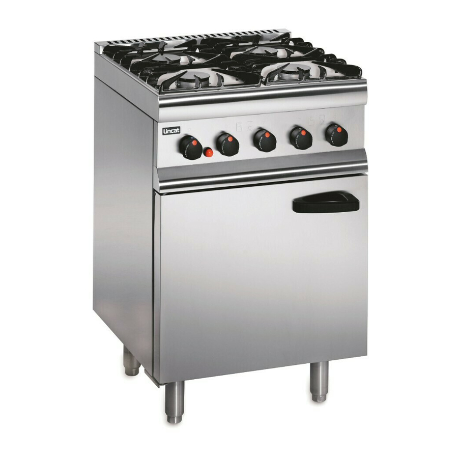
Silverlink 600 Gas Ranges
SLR6, SLR6C, SLR9 and SLR9C
Please make a note of your product details for
future use:
Date Purchased:
Number:
Dealer:
IS514 ECN4292
_
_
_
Page 1 of 20
Table of
Contents
Previous
Page
Next
Page
1
2
3
4
5
Advertisement
Table of Contents
Need help?
Do you have a question about the SLR6 and is the answer not in the manual?
Ask a question
Questions and answers
Related Manuals for Lincat SLR6
Oven Lincat SLR6 Installation, User & Servicing Instructions
(13 pages)
Cooktop Lincat Silverlink 600 Series Installation, Operating, Servicing And Conversion Instructions
Gas boiling tops (16 pages)
Grill Lincat Silverlink 600 Series User, Installation And Servicing Instructions
Gas salamander grills (14 pages)
Commercial Food Equipment Lincat Silverlink 600 Series Installation, Operating And Servicing Instructions
Heated and ambient pedestals (8 pages)
Ranges Lincat SLR9C Installation, Operating, Servicing And Conversion Instructions
(20 pages)
Ranges Lincat SILVGRLINK 600 Installation, User And Servicing Instructions
Oven range (8 pages)
Ranges Lincat OD7006 User, Installation, Servicing And Conversion Instructions
Dual fuel oven ranges (19 pages)
Ranges Lincat Opus 700 OE7008 User, Installation And Servicing Instructions
Electric oven ranges (15 pages)
Ranges Lincat Phoenix PHER01 Installation & Operating Instructions Manual
Electric induction range (14 pages)
Ranges Lincat OE7010 User, Installation And Servicing Instructions
Electric oven ranges (16 pages)
Ranges Lincat OE8017 Installation, Operating And Servicing Instructions
Electric induction range (10 pages)
Ranges Lincat Phoenix PHER01-A002 Installation & Operating Instructions Manual
Electric induction range (13 pages)
Ranges Lincat Opus 800 Series Installation, Operating, Servicing And Conversion Instructions
Gas open top oven ranges (24 pages)
Ranges Lincat Opus 800 Installation, Operating And Servicing Instructions
Gas solid top range (20 pages)
Ranges Lincat OG7001 User, Installation, Servicing And Conversion Instructions
Opus 700 gas oven ranges (15 pages)
Ranges Lincat Opus 800 OG8001/N Installation, Operating, Servicing And Conversion Instructions
Gas open top oven ranges (20 pages)
This manual is also suitable for:
Slr9
Silverlink 600 series
Slr9c
Slr6c
Table of Contents
Print
Rename the bookmark
Delete bookmark?
Delete from my manuals?
Login
Sign In
OR
Sign in with Facebook
Sign in with Google
Upload manual
Upload from disk
Upload from URL


Need help?
Do you have a question about the SLR6 and is the answer not in the manual?
Questions and answers