Page 1
Installation, Operating, Servicing and Conversion Instructions 
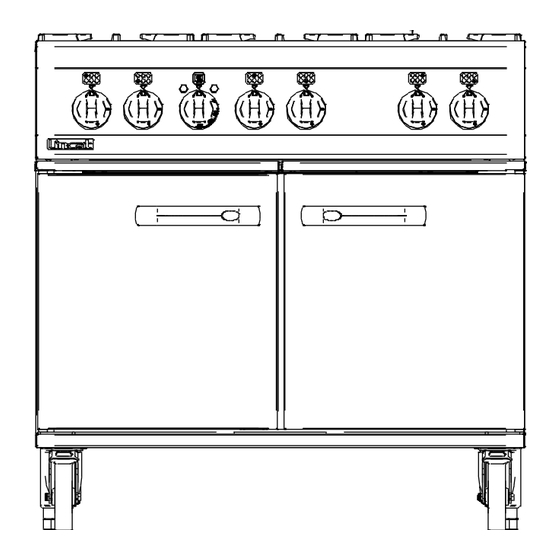
Opus 800 Dual Fuel Ranges OD8006-A002 & OD8007-A002 Please make a note of your product details for future use: Date Purchased:_________________________ Model Number:__________________________ Serial Number:__________________________ Dealer:_________________________________ _______________________________________ IS642 ECN 4259 Page 1 of 20...
WARNING! This symbol is used whenever there is a risk of personal injury. CAUTION! This symbol is used whenever there is a risk of damaging your Lincat product. NOTE: This symbol is used to provide additional information, hints and tips.
WARNINGS AND PRECAUTIONS This appliance must be installed, commissioned, serviced and converted by a qualified person in accordance with national and local regulations in force in the country of installation. Strip plastic coating and clean the appliance before use. During operation parts may become hot - avoid accidental contact. Parts protected by the manufacturer shall not be adjusted by the user.
TECHNICAL DATA Model OD8006 OD8007 Dimensions Height (mm) Width (mm) Depth (mm) Weight (kg) Hob Cooking Surface w x d (mm) 600 x 600 900 x 600 Useable Oven Capacity w x d x h (mm) 500 x 540 x 400 715 x 540 x 400 Oven Shelf w x d (mm) 500 x 540...
INSTALLATION AND COMMISSIONING Site this appliance beneath an extraction canopy for the removal of combustion products. When making the gas connection, fit an isolating cock into the supply line close to the appliance for emergency shutdown or servicing purposes. Installation must include sufficient ventilation to prevent the occurrence of unacceptable concentrations of substances harmful to health in the room of installation.
Page 7
SITING The installer must ensure that all regulations are met and that there is an unobstructed minimum distance of 1000mm from the top of the flue to the ceiling, which must be of non-combustible material. The appliance should be installed on a level surface ensuring the unit is stable and firmly located.
OPERATING INSTRUCTIONS This appliance is only for professional use and should only be used by qualified personnel. Ensure that the person responsible understands how to light, safely operate, clean and shut down the appliance and is made aware of the position and operation of the gas isolating cock in the event of an emergency.
Your Lincat product has a manufacturer’s warranty. This requires you to maintain and care for your product and follow maintenance instructions. If you fail to maintain your unit or damage components Lincat may charge you for a warranty repair. Please check the website for terms and conditions.
Page 10
Pan Support Channel – Remove from the appliance taking note of its fixing points. Hob Burner Components Part Description Pan Support Channel Fig. 4 The Pan Support Channel can be cleaned with a mild detergent and hot water solution using a soft bristled brush. Rinse and dry thoroughly with a dry cloth. Hob Burner Components Part Description...
Page 11
Oven Components. Oven Shelves & Side Hangers – Open the oven doors and remove the shelves and hangers. To remove shelves, tilt up the rear and slide shelf forward. To remove side hanger, lift hanger up and then pull into centre of oven. Fig.
SERVICING, MAINTENANCE AND COMPONENT REPLACEMENT All servicing, maintenance and component replacement on this appliance should be carried out by one of our recommended service engineers. SERVICE ACCESS To access and service the gas control valves – Recommended every 6 months ...
Page 13
COMPONENT REPLACEMENT Hob Thermocouple Remove the pan supports AA. Remove the top thermocouple lock nut. Remove thermocouple nut from valve body B and withdraw the thermocouple. Fit the new thermocouple and re-assemble in the reverse order. Control Valve Remove the control knobs CC, pan supports AA, and fascia panel BB. Remove the nut from the gas output at the valve.
Page 14
Control Thermostat/Fan Switch Remove the pan supports AA, covers, burner caps NN and burner bodies MM from the LH side of the appliance. From inside the oven remove the thermostat phial from its bracket and push up through the oven roof. Remove the fascia (see page 12).
Page 15
Contactor Working from the rear of the appliance, remove the rear cover C1. Remove the connections from the contactor and connect to new contactor. Unclip the contactor and clip new contactor into the bracket. Refit components in reverse order. Oven Fans Remove the oven shelves (see page 11).
FAULT FINDING Please refer to the Service Help Desk number on the final page of this manual. Burner/s will not light or stay lit Is there gas at the burner? Check injector for blockages Are thermocouple connections loose? Tighten connections Is the thermocouple voltage less than 15mV? Replace thermocouple Is the valve damaged?
SPARE PARTS LIST Part number Part description OD8006 OD8007 BU55 Door bushes BU72 Door bushes BU103 Burner cap BU104 Burner body BU106 Injector housing BU107 Elbow BU108 Venturi CA143 125mm braked swivel castors CA145 125mm un-braked swivel castors CO215 Contactor DO211 Door catch assembly Element –...
Type number Serial number Lincat reserve the right to carry out any work under warranty, given reasonable access to the appliance, during normal working hours, Monday to Friday, 08:30 to 17:00. DECLARATION All Lincat products capable of burning gaseous fuels, satisfy the requirements of the Gas Appliance Regulations 2016/426.
Need help?
Do you have a question about the Opus 800 and is the answer not in the manual?
Questions and answers