Table of Contents
Advertisement
Quick Links
Users manual and
parts book
Eliminator
Serial number:
Translation of the original operating
instructions
ATTENTION:
FOR SAFE USE OF THE MACHINE AND FOR THE BEST RESULTS IT IS VERY
IMPORTANT THAT THIS USER'S MANUAL IS READ METICULOUSLY BEFORE USE
OF THE ELIMINATOR.
0948 English 949.120.200
Kwekerijweg 8
3709JA Zeist
The Netherlands
T: (31)306933227
F: (31)306933228
E:
verti-drain@redexim.com
www.redexim.com
Advertisement
Table of Contents

Related Manuals for Redexim Eliminator


Summary of Contents for Redexim Eliminator
- Page 1 Serial number: www.redexim.com Translation of the original operating instructions ATTENTION: FOR SAFE USE OF THE MACHINE AND FOR THE BEST RESULTS IT IS VERY IMPORTANT THAT THIS USER’S MANUAL IS READ METICULOUSLY BEFORE USE OF THE ELIMINATOR. 0948 English 949.120.200...
-
Page 2: Preface
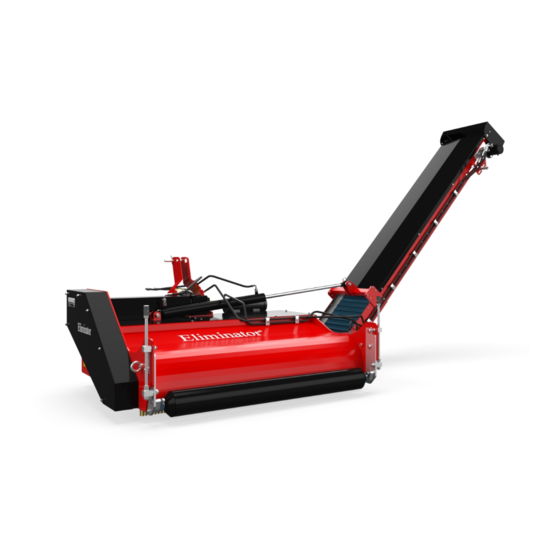
Without full knowledge of the contents it is impossible to work with this machine safely. The Eliminator is a machine designed for removing infill from artificial turf fields. The Eliminator has no receiving bin of its own so another machine will have to be used to catch the infill removed. -
Page 3: Safety Instructions
Making alterations or additions to the Eliminator (excluding those approved by the manufacturer) are not permitted, in principle, for safety reasons. If modifications to the Eliminator have been made, then the current CE mark is cancelled and whoever made these modifications must apply for a new CE mark... - Page 4 Before work is done to it, the pressure should always be taken off the hydraulic installation. In the absence of protective covers and safety stickers the Eliminator must NEVER be used. When using the Eliminator all protective covers for the machine MUST be fitted.
- Page 5 When using the public highway the applicable traffic regulations also apply. Transporting people is not permitted! Do not use the Eliminator in the darkness, during heavy rainfall / storms or on slopes with an angle over 20 degrees. Before commencing the work, all persons who will operate the Eliminator must be familiar with all its functions and operational elements.
- Page 6 Wear functional clothes. Wear heavy shoes with steel toecaps, long trousers, long hair done up and no loose-fitting clothes. Use the proper personal protective equipment according to the applicable safety instructions. Fig. 5 Position of safety stickers. (Fig. 5)
-
Page 7: Table Of Contents
COUPLING TO THE TRACTOR ..................11 THE PTO ........................12 LENGTH OF THE PTO (fig. 8) ..................12 USE OF THE PTO ......................13 PTO INFORMATON AND MAINTENANCE ..............13 OPERATION OF THE ELIMINATOR ................14 START/STOP PROCEDURE ..................14 DRIVING SPEED ......................15 SETTING WORKING DEPTH ..................16 ADJUSTING V-STRING TENSION .................17 CONVEYOR BELT ALIGNMENT ..................18... -
Page 8: Technical Data
TECHNICAL DATA Model Eliminator Working width 1500 mm 0mm - 40mm (0”-1.5”) Working depth (With brush not worn out) Driving speed 0 - 5 Km/h 0 - 3 mph Weight 600 Kg (1320 lbs) Recommended tractor 35 HP. Lifting capacity 900 kg (1984 lbs). -
Page 9: First Installation, Taking The Machine Off The Pallet
FIRST INSTALLATION, TAKING THE MACHINE OFF THE PALLET Fig. 6 The machine is delivered on a pallet with the supply belt in transport position. To remove the pallet and prepare the machine, proceed as follows (see fig.6) !! NEVER CRAWL UNDER THE MACHINE !! 1. -
Page 10: General Parts List
GENERAL PARTS LIST In figure 8 some important parts are shown: 2 10 Fig. 7 Safety sticker 900.280.402, read users manual before use/ toolbox. Safety sticker 933.280.402, for bystanders without personal protective equipment keep a 4 metre distance from the machine. Watch out for material flying about! All safety stickers must be attached to the machine at all times and must be understood. -
Page 11: Coupling To The Tractor
Without them the machine must NEVER be used. Fig. 9 The Eliminator can be coupled to the tractor by means of the 3-point linkage. The method is as follows: (Fig. 9) 1. Remove the 3-point pins 1 and 2 2. -
Page 12: The Pto
LENGTH OF THE PTO (fig. 8) The length of the PTO is very important. If it is too long, the drive of the tractor and/or Eliminator can be damaged. If the overlapping length of the cylinders is less than 150 mm (6”) at any time, the PTO can be damaged. -
Page 13: Use Of The Pto
USE OF THE PTO For proper use of the PTO the following items must be checked: 1. During operation of the Eliminator the angle of the turning points must never exceed 30 degrees. 2. The turning points must always be in line. -
Page 14: Operation Of The Eliminator
Thee start procedure is as follows: (see Fig. 10) 1. Check the Eliminator thoroughly for loose parts and check whether all parts are functioning properly. !! If loose parts have been found or if parts do not work properly, then the problems need to be solved first before using the Eliminator !! 2. -
Page 15: Driving Speed
10. Now drive forward and increase the speed to, at most, 5 Km/h (3 mph). See chapter 6.2. 11. Make sure the Eliminator moves at a speed equal to that of the external receiving bin. 12. If the desired depth is not achieved, adjust the brush to a greater depth and restart the treatment. -
Page 16: Setting Working Depth
The procedure is as follows: (see fig.11) !! Make sure that the tractor/Eliminator is blocked properly and cannot move of its own accord !! !! Switch off the tractor before getting off !! 1. -
Page 17: Adjusting V-String Tension
ADJUSTING V-STRING TENSION Fig. 12 The Eliminator is equipped with a standard adjustable tensioning roller that keeps the v-strings under tension. As the machine is used, wear and tear occurs on the drive line. Because of this it may occur that the v-strings start to slip and must be retensioned. -
Page 18: Conveyor Belt Alignment
CONVEYOR BELT ALIGNMENT Fig. 13 If the conveyor belt starts slipping or moving sideways after a while or after new installation, please use the instruction as described below for re-tensioning: (See fig. 1) 1. At first check if the rollers and inside of the conveyor belt are clean. If necessary clean the polluted parts. -
Page 19: Transport Of The Eliminator
Work Position Fig. 14 The user is responsible for the transportation of the Eliminator behind the tractor on the public highways. Check the national laws regarding regulations. Over open fields, with the machine lifted, the speed must not exceed a maximum of 20 km/hour (12.4 mph), because of the Eliminator’s weight. -
Page 20: Maintenance
MAINTENANCE Time-line Check point/Greasing Method point Before every use. Check for loose bolts / nuts. Tighten the loose bolts/nuts with the right torque Presence and Legibility of safety Replace these if not stickers. present/damaged. (Fig. 7) Check for hydraulic defects. If necessary, repair or replace damaged parts. -
Page 21: Problem Analyses
10.0 EU STATEMENT We – Redexim BV, Utrechtseweg 127, 3702 AC Zeist, Holland – declare entirely under our own responsibility that the product TURF-STRIPPER WITH A MACHINE NUMBER AS INDICATED ON THE MACHINE AND INDICATED IN THIS MANUAL...
Need help?
Do you have a question about the Eliminator and is the answer not in the manual?
Questions and answers