Table of Contents
Advertisement
User Manual and Parts Book
Verti-Drain
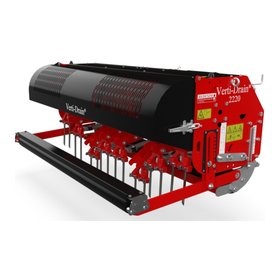
Model 2216
Model 2220
Serial number:
Translation of the original operating instructions
ATTENTION:
IT IS OF THE UTMOST IMPORTANCE TO READ THIS USER MANUAL
CAREFULLY PRIOR TO USING THE VERTI-DRAIN
USE THE MACHINE SAFELY AND TO OBTAIN THE BEST RESULTS.
®
1703 English 911.120.202
Kwekerijweg 8
3709JA Zeist
The Netherlands
T: (31)306933227
F: (31)306933228
E:
verti-drain@redexim.com
www.redexim.com
®
IN ORDER TO
Advertisement
Table of Contents

Related Manuals for Redexim Verti-Drain 2216


Summary of Contents for Redexim Verti-Drain 2216
- Page 1 Model 2216 Kwekerijweg 8 3709JA Zeist Model 2220 The Netherlands T: (31)306933227 F: (31)306933228 verti-drain@redexim.com www.redexim.com Serial number: Translation of the original operating instructions ATTENTION: IT IS OF THE UTMOST IMPORTANCE TO READ THIS USER MANUAL ® CAREFULLY PRIOR TO USING THE VERTI-DRAIN IN ORDER TO USE THE MACHINE SAFELY AND TO OBTAIN THE BEST RESULTS.
-
Page 2: Foreword
FOREWORD ® Congratulations on your Verti-Drain purchase! For safe and long-lasting operation of this ® Verti-Drain , it is necessary to read and to understand this user manual. It is impossible to work safely with this machine without complete knowledge of its content. ®... -
Page 3: Safety Instructions
SAFETY INSTRUCTIONS ® The Verti-Drain is designed for safe use. This can only be achieved if you completely follow the safety instructions described in this manual. Read and understand the manual before (Figure 1) ® you start using the Verti-Drain If the machine is not used as described in this Figure 1 manual, this can result in injuries and/or damage... - Page 4 If present, check the hydraulic pipelines regularly and replace these when the hydraulic pipelines are damaged or appear old. The pipelines that are replaced should comply with the technical requirements of the manufacturer. If a hydraulic installation is present, you should always make it pressure-free before working on this installation.
- Page 5 All persons that are going to operate the Verti-Drain® must be familiar with all the functions and control elements of the Verti-Drain® before starting any work activities. ® Attach the Verti-Drain to the towing vehicle according to the regulations. Check whether you have a clear field of vision – both close by and far away – before you depart.
- Page 6 Location of the safety stickers (Figure 7) Figure 7 Used oil/grease is harmful to the environment. Dispose of these substances according to the regulations that apply in your location.
-
Page 7: Eu Declaration
EU DECLARATION We – Redexim BV, Utrechtseweg 127, 3702 AC Zeist, Holland – declare entirely under our own responsibility that the product VERTI-DRAIN® WITH A MACHINE NUMBER AS INDICATED ON THE MACHINE AND INDICATED IN THIS MANUAL to which this declaration refers, complies with stipulation of the 2006/42/EC machine... -
Page 8: Table Of Contents
TABLE OF CONTENTS FOREWORD ......................2 REGISTRATION CARD ..................... 2 SAFETY INSTRUCTIONS ..................3 EU DECLARATION....................7 TECHNICAL DATA ..................9 GENERAL DESCRIPTION ................10 FIRST INSTALLATION – TAKING THE MACHINE OFF THE PALLET AND ATTACH TO THE TRACTOR ...................10 ... -
Page 9: Technical Data
TECHNICAL DATA Model 2216 2220 Working width 1.60 m (63”) 2.08 m (82”) Working depth Up to 225 mm (9”) Up to 225 mm (9”) Tractor speed measured at 540 rpm on the PTO: Hole distance 65 mm Up to 1.79 km/h (1.1 mph) (2.6”) Up to 2.48 km/h (1.5 mph) Hole distance 90 mm (3... -
Page 10: General Description
Optional Solid pins Hollow pins Turf hold-down fingers Windrow kit Hydraulic front roll adjustment GENERAL DESCRIPTION ® ® The Verti-Drain is a machine for aerating grass and sport fields. The Verti-Drain is a 3- ® point machine. -
Page 11: The Power Take Off (Pto)
Assemble the PTO Cover 2 that is included with the supplied items. Attach the machine to a tractor. Use the proper tractor (please refer to the specifications). 10. Attach the hydraulic hoses to the tractor. 11. Lift the machine off the ground. 12. -
Page 12: Using The Pto
In order to set the PTO on the correct length, when a new one has been purchased or when a different tractor is used, follow these steps: (see Figure 9) Measure the distance between the PTO’s connection to the tractor and to the Verti-Drain, from groove to groove, when the machine is connected to the tractor and positioned on the ground at the right angle. - Page 13 If the coupling slips, stop the motor after 10 seconds. If the coupling does not slip, loosen up the bolts further or proceed with the maintenance / annual maintenance task (see point 4 below). As soon as the coupling has slipped, screw the bolts/nuts tight until you see that the slip coupling is once again functioning properly.
- Page 14 Fig. 10...
-
Page 15: Adjusting The Working Depth
ADJUSTING THE WORKING DEPTH The working depth can be adjusted when the machine is lifted, see Figure 10. Tighten the nuts one by one turn on both sides of the machine. Then turn on or off spindle 3. The sticker 2 on the side of the machine, the depth setting. If the correct working depth is reached, tighten the nuts 1 again. -
Page 16: Driving Speed
DRIVING SPEED km/h 2,18 2,50 2,02 3,25 1,86 3,00 1,71 2,75 1,55 2,50 1,40 2,25 1,25 2,00 1,10 1,75 0,95 1,50 0,80 1,25 0,64 1,00 0,48 0,75 0,32 0,50 0,16 0,25 inch Figure 11 The driving speed determines the distance D between the holes in the driving direction (see Figure 11). -
Page 17: Start Procedure
START PROCEDURE Figure 13 The start procedure is VERY important. If this procedure is not executed as described below, it might result in serious damage to the machine. The start procedure is as follows (see Figure Move to the location where you want to start. Lower the machine until the lower pins almost touch the ground. -
Page 18: Using The Verti-Drain
USING THE VERTI-DRAIN® ® Before using the Verti-Drain in a location, you should check the following items: Are there loose objects in the field? First remove these objects. Are there slopes? The maximum slope is 20 degrees for this machine. Always go from top to bottom. -
Page 19: Trouble Shooting (Problem Analysis)
12.0 TROUBLE SHOOTING (PROBLEM ANALYSIS) Problem Possible cause Solution Machine vibrates. Crankshaft turns irregularly. Machine is not set to 90°. Angles of the PTO’s turning points are different. PTO’s turning points are not Difficult conditions aligned. Adjust the working depth. Use shorter/thinner pins. -
Page 20: Maintenance
Problem Possible cause Solution Crankshaft problems Big-end nuts come undone. Rectify the vibration (see vibration) Crankshaft bearing is worn. Incorrect assembly after repair. Remove, clean and use Loctite. Rear roller vibrates. Locked rear roller. Unlock. Rear roller is in upward Change the speed and the PTO position during pricking with revs. -
Page 21: Technical Information: Grease Points
Time schedule Check/Grease point Method Loose hanging parts around the Tighten the parts so that After the first 20 working hours (new or repaired) they cannot reach the PTO Grease PTO, roller bearings and Use EP2 grease After every 50 working hours crankshaft bearings. -
Page 22: The Crankshaft
14.1 THE CRANKSHAFT Figure 14 illustrates the composition of the crankshaft. Also look at the Parts page for a more detailed drawing. In this machine the angle between the crank cheeks on the gearbox must be 0°. 14.2 REPLACING A CRANK / CRANK BEARING Replacing a crank is necessary if the crank is cracked or if the big-end nuts come undone regularly. - Page 23 If the parts in the crankshaft are replaces, the crankshaft can run heavier. Pre-tension can be the cause. It is necessary to eliminate these tensions as follows (see Figure 14): Loosen the nuts (3) of the bearing blocks (4)a few turns. From the centre of the gearbox, tighten the bearing blocks (4) one by one.
- Page 24 Fig. 15...
-
Page 25: Timing And Tightening Moments
14.5 TIMING AND TIGHTENING MOMENTS Figure 15 indicates the tightening moments of the major bolts and nuts. Make sure that the tightening moments of bolts and nuts, which are not listed in Figure 15, are the same as the tightening moments of comparable bolts and nuts. If bolts and nuts come undone, Loctite may be used to tighten them. - Page 26 Pins are vital for the proper functioning of the machine. Different pins are available for this machine. See the Parts page for a complete overview. Generally speaking, the pins can be divided into two categories: solid and hollow pins. We recommend using only original pins, because they are completely adjusted to the machine.
-
Page 27: Option: Windrow Kit
Always use pins of the same thickness and length. Replace a bent pin immediately. If you don’t do this, the machine can become unstable. Do NOT use thicker and/or longer pins than the ones we supply. Shorter (worn) pins can be used if superficial pricking is required. Be aware of the fact that the working depth indicated on the sticker will only be correct if the maximum length of the pin is used. -
Page 28: Option: Hydraulic Depth Adjustment
15.3 OPTION: HYDRAULIC DEPTH ADJUSTMENT The machine is equipped with a standard mechanical depth adjustment. If desired, the machine can be converted to a hydraulic depth adjustment. The hydraulic depth adjustment can be ordered as an option with number: VD2216: 211.116.006 ... - Page 29 If there is still air in the machine, repeat 3 to 5 until all air is removed. The system is now vented and ready for use. Ensure that both sides of the machine are moving up and down parallel to each other.
- Page 31 Parts manual...
- Page 32 Redexim Verti-Drain 2216/2220 Pag 01 Code 1213 Page 02: Decalls Page 03: Covers Page 04: Rear roller Page 05: Front roller Page 06: Element VD2220-PP INDEX.dwg...
- Page 33 Redexim Verti-Drain 2216/2220 Pag 01 Code 1213 Page 07: Crankshaft Page 08: Gearbox Page 09: Central Bar Page 10: Drawrod Page 11: Option Hydraulic height adjustment Page 12: Option Windrow kit Page 13: Tines Page 14: Adapters and turf hold down kits Page 15: PTO VD2220-PP INDEX.dwg...
- Page 34 Redexim Verti-Drain 2216/2220 Pag 02 Code 1213 VD2220-PP01.dwg...
- Page 35 Redexim Verti-Drain 2216/2220 Pag 02 Code 1213 PART # DESCRIPTION REMARKS QUA 2216 QUA 2220 911.260.402 Label Verti-Drain 911.260.200 Label 2220 911.260.202 Label 2216 911.280.402 Safety decall VD 911.280.404 Close Cover 900.280.404 Cut off fingers 900.260.422 Decall PTO 350 540 900.280.402...
- Page 36 Redexim Verti-Drain 2216/2220 Pag 03 Code 1638 VD2220-PP02.dwg...
- Page 37 Redexim Verti-Drain 2216/2220 Pag 03 Code 1638 PART # DESCRIPTION REMARKS QUA 2216 QUA 2220 404.140.100 Distance Bush 446.080.550 Rubber stop 456.213.033 Weld Assy Cover 456.158.037 Weld Assy Cover 464.040.850 Cover bracket 464.041.450 Bracket cover 464.041.800 Cover bracket 468.022.602 Protection cover 468.025.700...
- Page 38 Redexim Verti-Drain 2216/2220 Pag 04 Code 1638 VD2220-PP03.dwg...
- Page 39 Redexim Verti-Drain 2216/2220 Pag 04 Code 1638 PART # DESCRIPTION REMARKS QUA 2216 QUA 2220 742.250.360 Bearing UCFL 205 404.140.150 Distance Bush 20/ 14, L= 15 404.140.160 Distance Bush 20/ 14, L= 16 406.150.320 Distance Bush 20/ 14.5, L= 32 446.100.100...
- Page 40 Redexim Verti-Drain 2216/2220 Pag 05 Code 1224 29 18 26 30 VD2220-PP04.dwg...
- Page 41 Redexim Verti-Drain 2216/2220 Pag 05 Code 1224 PART # DESCRIPTION REMARKS QUA 2216 QUA 2220 464.156.250 Front Roller Support 468.063.040 Mounting strip THD Beam 470.109.205 THD Beam 470.109.153 THD Beam 488.194.207 Weld Assy Front Roller 488.194.154 Weld assy Front Roller 742.302.400...
- Page 42 Redexim Verti-Drain 2216/2220 Pag 06 Code 1638 VD2220-PP05.dwg...
- Page 43 Redexim Verti-Drain 2216/2220 Pag 06 Code 1638 PART # DESCRIPTION REMARKS QUA 2216 QUA 2220 2661700 Distance washer Qua for 1 element 4001675 Tine holder bolt Qua for 1 element 4002315 Tine holder bolt M16 Qua for 1 element 406.250.250...
- Page 44 Redexim Verti-Drain 2216/2220 Pag 07 Code 1638 14 15 (Set screw) VD2216 120° angle between crank VD2216 90° angle between crank (shown), more details see chapter 14 users manual. VD2220-PP06.dwg...
- Page 45 Redexim Verti-Drain 2216/2220 Pag 07 Code 1638 PART # DESCRIPTION REMARKS QUA 2216 QUA 2220 406.450.140 Distance Bush Ø60/Ø45,2 L=14 406.460.222 Distance Bush Ø60/Ø45,2 L= 22 406.460.320 Distance Bush Ø60/Ø45,2 L=32 880.060.100 Grease nipple M6 DIN 71412A 4067000 Breather for bearing support...
- Page 46 Redexim Verti-Drain 2216/2220 Pag 08 Code 1638 33 32 VD2220-PP07.dwg...
- Page 47 Redexim Verti-Drain 2216/2220 Pag 08 Code 1638 PART # DESCRIPTION REMARKS 2505477 Side gear Z=47 2506825 Side gear Z=40 2544500 Pignon wheel with shaft 4109600 Crank shaft nut M40 x 1.75 416.451.630 Big end pin 420.452.040 Splined Shaft 4408930 Seal ring 60x80x10...
- Page 48 Redexim Verti-Drain 2216/2220 Pag 09 Code 1638 VD2220-PP08.dwg...
- Page 49 468.101.002 Lock plate 494.206.202 Central bar 494.206.150 Central bar 494.212.820 Frame Verti-drain 2220 494.160.820 Frame Verti-drain 2216 521.221.600 3-Point Pin 523.040.700 R-Pin 4, DIN 11024 802.080.350 Bolt DIN 931-1 - M8 x 35 802.080.450 Bolt DIN 931-1 - M8 x 45 802.160.800...
- Page 50 Redexim Verti-Drain 2216/2220 Pag 10 Code 1646 Apply 40ml MP grease mm To calibrate with 864.080.054 VD122.020 - PP 22-1.dwg...
- Page 51 Redexim Verti-Drain 2216/2220 Pag 10 Code 1646 PART # DESCRIPTION REMARKS 2602454 Plastic Guide Bush 404.160.050 Distance bush Ø65/Ø38/Ø16 L=5.25 404.160.070 Distance bush Ø65/Ø38/Ø16 L=7.25 406.160.130 Distance bush Ø30/Ø16 L=13 444.350.350 Slider bush 446.400.500 Rubber stop 448.421.150 Draw Rod Head With Stud...
- Page 52 Redexim Verti-Drain 2216/2220 Pag 11 Code 1525 14mm(0.55") Strips already on machine. See page 05. Apply hose clamps on pre-drilled holes of cover Re-use bolt, washer and nut as standard on both sides of the machine. See page 5. 8 29 13...
- Page 53 Redexim Verti-Drain 2216/2220 Pag 11 Code 1525 PART # DESCRIPTION REMARKS QUA 2216 QUA 2220 404.170.690 Distance Bush Support 404.201.020 Bush 464.043.100 Guide strip 468.013.400 Shim plate 534.252.002 Hydraulic cylinder 40 x 25, Stroke 200mm 534.252.004 Hydraulic cylinder 50 x 30, Stroke 200mm 535.401.000...
- Page 54 Redexim Verti-Drain 2216/2220 Pag 11A Code 1525 Placement of bracket 468.031.402 (Cover, Cylinder and hoses hidden) Apply threadlocking sealant Apply threadlocking sealant Setup dimensions pointer 11mm (0.43") Apply threadlocking sealant 12mm (0.5") VD2220-PP11a.dwg...
- Page 55 Redexim Verti-Drain 2216/2220 Pag 11A Code 1525 PART # DESCRIPTION REMARKS QUA 2216 QUA 2220 468.031.402 Bracket 468.020.990 Support strip damper 468.026.740 Height indicator box 571.204.850 Damper, stroke 220mm 850.060.360 Fork 591.089.100 Cable height indicator 804.060.120 Bolt DIN 933 - M6 x 12 804.060.550...
- Page 56 Redexim Verti-Drain 2216/2220 Pag 12 Code 1213 Shown windrow kit for VD2220 13 11 VD2220-PP12.dwg...
- Page 57 Redexim Verti-Drain 2216/2220 Pag 12 Code 1213 PART # DESCRIPTION REMARKS QUA 2216 QUA 2220 468.089.000 Windrow Plate 468.085.500 Windrow Plate extension 406.130.150 Distance bush 830.120.120 SL Nut DIN 985 - M12 846.080.241 Dee (chain) shackle d8 864.100.031 Large Washer DIN 9021 - 10,5 406.170.150...
- Page 58 Redexim Verti-drain 2216 and 2200 Code 1638 Page 13 Solid tines 2216 2220 Mounting Ø (mm) Tine Size (mm) Tine Size (inch) Part # Adapter 5 x 125 3/16 x 5 311.105.125 J or multi-tine block mini 8 x 150 5/16 x 6 311.108.150...
- Page 59 Redexim Verti-drain 2216 and 2200 Code 1638 Page 14 Adapter 2216 2220 Tine Size (mm) Tine Size (inch) Part # 3/16 314.205.043 5/16 314.208.043 Adapter 2216 2220 Tine Size (mm) Tine Size (inch) Part # 2451800 Multi-tine block complete WO tines...
- Page 60 Redexim Verti-Drain 2216-2220 Page Code 1638 111PR001-PPPTO...
- Page 61 Redexim Verti-Drain 2216-2220 Page Code 1638 PART NUMBER DESCRIPTION REMARKS ITEM 190000016 Inner roll pin 190000018 Outer roll pin 141026108 Complete collar yoke type 60 151016028 Outer tube yoke type 60 151016029 Inner tube yoke type 60 153160150 T60-series Inner tube...
Need help?
Do you have a question about the Verti-Drain 2216 and is the answer not in the manual?
Questions and answers