
Related Manuals for Redexim VERTI-DRAIN 7117


Summary of Contents for Redexim VERTI-DRAIN 7117
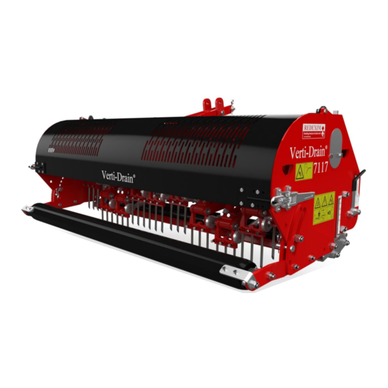
- Page 1 User manual VERTI-DRAIN 7117 Translation of the original user manual 2134 English 911.120.411 EN Kwekerijweg 8 | 3709JA | Zeist | The Netherlands | T: +31 (0)306 933 227 redexim@redexim.com www.redexim.com...
-
Page 2: Foreword
FOREWORD. Congratulations on the purchase of your VERTI-DRAIN. To ensure the safe and lasting operations of this VERTI-DRAIN you (and anyone using the machine) should read and understand this user’s manual. A complete knowledge of the contents of the manual is necessary in order to ensure the safe use of this machine. -
Page 3: Safety Instruction
SAFETY INSTRUCTIONS Always use the VERTI-DRAIN with the correct tractor as described in the technical information The user is responsible for a safe Tractor/VERTI-DRAIN combination. The combination must be tested for noise, safety, risk and easy usage. The VERTI-DRAIN is suited exclusively to grass fields. Every VERTI-DRAIN user must be fully informed of the information contained in the user manual. -
Page 4: Table Of Contents
CONTENTS. Paragraphe Description Page Foreword Guarantee conditions Registration card Safety instruction Technical specification First setup, lifting machine from pallet General controls PTO length Use of PTO Working depth adjustment Tine angle adjustment Groundspeed Starting procedures General usage of Verti-Drain 10.0 Transport of Verti-Drain 11.0 Uncoupling of the Verti-Drain... -
Page 5: Technical Specification
TECHNICAL SPECIFICATIONS. Model 7117 1.70 mtr (68”) Working width Up to 150 mm (6”) Working depth Tractor speed @ 500 rev’s at PTO Hole spacing 55 mm (2-1/8”) Up to 2.0 km/h (1.25 mph) Hole spacing 90 mm( 3 ½”) Up to 3.2 km/h (2.0 mph) Hole spacing 125mm(5”) Up to 4.3 km/h (2.7 mph) -
Page 6: First Setup, Lifting Machine From Pallet
2.0 FIRST SETUP, LIFTING MACHINE FROM PALLET The machine stands vertically up on the pallet. To remove the pallet and get the machine horizontal on the ground, handle as follows (see fig.1 ): 1. Open the rear cover 2. Connect a cable to lift point * ensure the cable/crane/lift truck can lift minimum 1000 Kg.(2200 lbs). -
Page 7: General Controls
3.0 GENERAL CONTROLS In fig.2. some key details of the machine are shown, as follows: 1. Safety decal RA, before using machine read manual. Decal is located at the toolbox with manual and combi-tool. -
Page 8: Pto
4.0 PTO. The PTO is a very important item. It drives the machine from the tractor and ensures the safe operations when correctly maintained and installed. The PTO shaft has its own CE certification. Read the PTO shaft manual, which is connected to the shaft itself For specific adjustments see the details given on the PTO page in the parts book. -
Page 9: Use Of Pto
4.2 USE OF PTO For the correct use of the PTO, the following items need to be checked: 1. During work the angle of the joints may never exceed 30 degrees 2. The joints have to be in line all the time 3. -
Page 10: Working Depth Adjustment
5.0 WORKING DEPTH ADJUSTMENT. The working depth can be adjusted when the machine is lifted from the ground as follows, see fig. 4: Unscrew nuts 1 at each side of the machine one turn. Screw spindle 3 in or out. Every revolution is 4 mm (0.160"). -
Page 11: Groundspeed
@ From 90 to 75 degrees means more "kick action". This is advised for solid tines, depending on ground conditions, tine size and customer requirements. @ The angle of 90 degrees means that the tines penetrate perpendicular into the ground. This is only true if the machine is correctly set, see fig.1. -
Page 12: Starting Procedures
8.0 STARTING PROCEDURES The starting procedure is VERY important. If the start up is not done as described hereunder, serious damage to the machine may occur. Proceed as follows, see fig.7.: 1. Drive to the spot you want to start the operation. 2. -
Page 13: General Usage Of Verti-Drain
@ Never drive backwards with the tines in or close to the ground. @ NEVER drive backwards, when the lowest tines are less than 120 mm (5") above the ground. If the tines get caught, serious damage will appear on the machine. @ Do not use a hydraulic top link. -
Page 14: Problem Analysis
12.0 PROBLEM ANALYSIS Machine vibrates Crankshaft rotates irregular Machine not at 90 degrees PTO joint angles different PTO joints not in line Tough circumstances Adjust working depth Use thinner/ shorter tines If dry, irrigate first Solid/ hollow tines Wrong tine Change tine, use shorter one Are bending/ breaking Use solids first before hollow to... -
Page 15: Maintenance
Use 80W90 (3 liters). hours. gearbox. 14.0 EU-Declaration We, Redexim Utrechtseweg 127 3702 AC Zeist Holland, hereby declare fully on our authority that the product: VERTI-DRAIN 7117, WITH MACHINE NUMBER AS INDICATED ON THE MACHINE AND IN THIS MANUAL, to which this declaration relates is according to the stipulation of the 2006/42/EC directive for machines as well as the following standards: NEN-EN-ISO 12100 : 2010 and NEN-EN-ISO 13857 : 2008. -
Page 16: Technical Information
15.0 TECHNICAL INFORMATION. Generally speaking, this Verti-Drain is not a complicated machine. A couple of technical items will be explained. If you still have questions, please contact your dealer, who is willing to assist you Fig. 8 In the above fig.8. the torque setting for the several bolts/nuts is given and the timing of the crankshaft. -
Page 17: Torque Settings
15.2 THE CRANKSHAFT In fig.9. the assembly of the crankshaft is given. Also look at the spare part page for a more clear view and setup. On a Verti-Drain 7117 the angle between the handles on the gearbox should be 33,75 degrees. -
Page 18: Replacing Of A Crank And Crank Bearing
15.2.2. REPLACEMENT OF A CRANK WITH BEARING Replacing a crank is necessary when it is cracked or when the big end nuts start to come loose on a regular bases. Either the crank bearing, the crank bearing fitting or the big end pin holes in the crank are damaged. -
Page 19: Assembly Of The Crown Wheel And Pignon
15.4 ASSEMBLY OF THE CROWN WHEEL AND PIGNON 1. Assemble the pignon wheel H, making sure to have the roller bearings unit positioned on the cir-clip side. (see fig. 10) 2. Mount both bearings B into the bearing Houses C. 3. - Page 20 Fig. 10...
-
Page 21: Options, Tines
The rear roller may not be locked. Use always tines with the same length and size. Replace a bent tine immediately. When this is not done, the machine can be unstable. Don’t use any thicker/ longer tines as what is offered by Redexim. -
Page 22: Hollow Tines
@ It is advisable using the dirt protection plates B1 (see fig. 11), that prevents the cores from entering the machine. This part has number 318.302.150. 16.1 OPTIONS, CORE COLLECTOR. An easy mountable core collector is available for the Verti-Drain 7117. The part number is 9300080. ASSEMBLING INSTUCTIONS (see Fig 12):... - Page 23 Assembling the core collector itself: Assemble supports 17 with eye bolts 9 and nuts 10/11 to the main collector plate 1 Screw the side panels 2/3 with bolts 7 and Bushes 8 to the main collector plate 1 Assemble the rubber strip 12 with bolts 13, washers 14 and nuts 6 to the plate 1 Assemble all the sheet springs 4 , well aligned, to the main plate 1.
-
Page 24: Options, Turf Hold Down Kit
The core collector can collect the core for a certain pass length. The length depends on the amount of cores and the sizes. If the area isn’t clean, check the gap between the rubber seal strip 12 and the blade spring tension 4. -
Page 25: Options, Windrow Kit
16.3 OPTIONS, WINDROW KIT. An optional windrow kit can be purchased, see fig. 14. The kit has the following part-number: 211.731.010. A detailed guide on how to assemble the kit can be found in the part pages of this manual. MOUNTING INSTRUCTIONS (see fig.
Need help?
Do you have a question about the VERTI-DRAIN 7117 and is the answer not in the manual?
Questions and answers