Advertisement
Advertisement

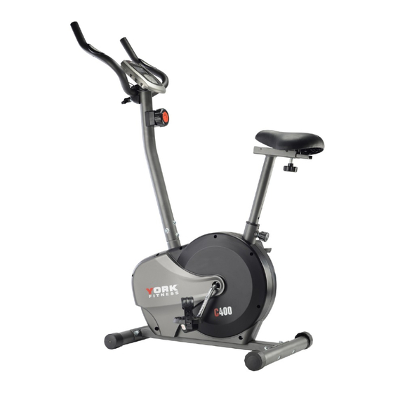
Related Manuals for York Fitness C400


Summary of Contents for York Fitness C400
- Page 1 Owner’s Manual C400 Upright Bike Item #YRK53098A www.yorkfitness.com.au...
-
Page 2: Table Of Contents
Table of contents Congratulations on CONTENTS purchasing your exercise equipment from Safety information Pre-Assembly List Part List Exploded Diagram You have chosen a high quality, safe and innovative piece of equipment as your training partner and we are certain it will keep you motivated on the way to Assembly Instructions achieving your personal fitness goals. -
Page 3: Safety Information
• Due to our continuous policy of product development, • Use only the adjustment setting as described in the York Fitness reserves the right to change instructions. Always use the correct adjustment specifications without notice. pin / fixing. •... - Page 4 IMPORTANT - Please retain your sales receipt, York Fitness Customer Care may request proof of purchase to validate eligibility for warranty service. Warranty cover starts from the date shown on the proof of purchase.
-
Page 5: Pre-Assembly List
Pre-Assembly Check List Before starting assembly, MAKE SURE YOU HAVE THE FOLLOWING PARTS PART NO. DESCRIPTION Q’TY Main frame Front post Seat post Front stabilizer Rear stabilizer Handlebar Pedal ( L ) Pedal ( R ) Seat Meter www.yorkfitness.com.au... - Page 6 Hardware Packing List DESCRIPTION DRAWING Carriage bolt M8*60 Φ8 Curved washer Domed nut M8 Allen bolt M8*16 Clamp cover T type knob Box Wrench Allen key L6...
-
Page 7: Part List
Parts List PART DESCRIPTION QUANTITY Main frame Front stabilizer Rear stabilizer End cap for front stabilizer End cap for rear stabilizer Carriage bolt M8*65 Curved washerΦ8 Domed nut M8 Allen bolt M8*16 Quick release knob Pedal ( L ) Pedal ( R ) Seat post Flat washer Φ17*Φ8 Spring washer Φ8... - Page 8 PART DESCRIPTION QUANTITY Chain cover (L) Chain cover (R) Self-tapping screw ST5*15 Self-tapping screw ST5*15 Belt pulley BB assembly Magnet assembly Magnet bushing Nut M8 Bolt M8*55 Belt Sensor bracket Hex head bolt M6*25 Hex head nut M6 Spring Flywheel Axle for flywheel adjusting bolt Bearing 6900...
-
Page 9: Exploded Diagram
Exploded Diagram www.yorkfitness.com.au... -
Page 11: Assembly Instructions
Assembly Instructions STEP 1 Attach the front stabilizer (2) to the front of the main frame (1), fasten with two carriage bolts (6), two curved washers (7) and two domed nuts (8). Attach the rear stabilizer (3) to the rear of the main frame (1), fasten with two carriage bolts (6), two curved washers (7) and two domed nuts (8). - Page 12 STEP 3 Take down the two cross-head screws (29) which are pre-assembled on the meter (18). Attach the handlebar (24) to the front post and fasten with one clamp (25), one allen bolt (26), one clamp cover (27) and one T type knob (28). Connect the upper sensor cable (32) to the sensor cable from the back of meter (18).
- Page 13 STEP 5 The pedals (11 & 12) are marked "L" and "R" - Left and Right. Connect them to their appropriate crank arms on the main frame. The crank right arm is on the right- hand side of the cycle as you sit on it. Note: the right pedal should be threaded on clockwise and the left pedal anticlockwise.
-
Page 14: Meter Instructions
Meter Instructions FUNCTIONAL BUTTONS: MODE - Push down for selecting functions. SET - To set the values of time, distance, calories and pulse when not in scan mode. RESET - Push down for resetting time, distance and calories. FUNCTION AND OPERATIONS: 1. -
Page 15: Exercise Instructions
Exercise Instructions Using your UPRIGHT BIKE will provide you with several benefits, it will improve your physical fitness, tone muscle and in conjunction with a calorie controlled diet help you lose weight. 1. The Warm Up Phase This stage helps get the blood flowing around the body and the muscles working properly. It will also reduce the risk of cramp and muscle injury. - Page 16 3. The Cool Down Phase This stage is to let your Cardio-vascular System and muscles wind down. This is a repeat of the warm up exercise e.g. reduce your tempo, continue for approximately 5 minutes. The stretching exercises should now be repeated, again remembering not to force or jerk your muscles into the stretch. As you get fitter you may need to train longer and harder.
-
Page 17: Warranty
WARRANTY, SAFETY AND ASSEMBLY INFORMATION YRK53098A– YORK C400 IMPORTANT Please read and retain this manual as it will assist with identification for parts and service. ------------------------------------------------------------------------------------------------------------ BOYLES FITNESS warrants their Cross Trainer to be free from defects in material and workmanship under normal use and service conditions. - Page 18 BFE Warranty Policy – November 1 2013 1. When purchased from an authorised BFE distributor the BFE warranty shall guarantee that all framework and components of your product are free from faulty manufacture. All faulty framework and components will be repaired or replaced as set out in this policy.
- Page 19 Returned Goods: The unauthorised return of parts or product shall be refused and placed in the hands of the carrier at the cost of the shipper. Return authorisations can be obtained from BFE head office only. Service Department hours: Monday to Friday between 9.00am and 4pm Service Phone Number: 07 3272 7010 PLEASE NOTE: that Authorised service technicians do not reside in all areas of this vast country.
- Page 20 www.yorkfitness.com.au...
Need help?
Do you have a question about the C400 and is the answer not in the manual?
Questions and answers