Advertisement
Advertisement
Table of Contents

Related Manuals for York Fitness C410


Summary of Contents for York Fitness C410
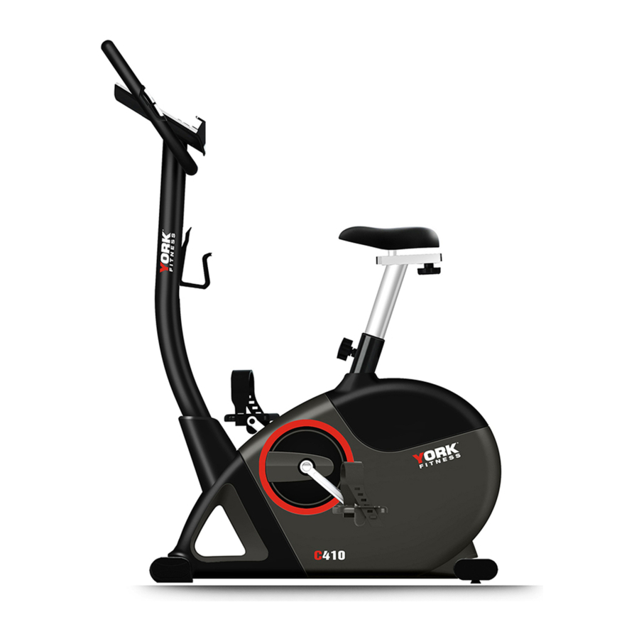
- Page 1 Owner’s Manual C410 Upright Bike Item #53100A www.yorkfitness.com.au...
-
Page 2: Safety Information
• Due to our continuous policy of product development, • Use only the adjustment setting as described in the York Fitness reserves the right to change instructions. Always use the correct adjustment specifications without notice. pin / fixing. •... -
Page 3: Customer Support
IMPORTANT!! - Please retain your sales receipt, York Fitness Customer Care may request proof of purchase to validate eligibility for warranty service. Warranty cover starts from the date shown on the proof of purchase. -
Page 4: Exploded Diagram
Exploded Diagram www.yorkfitness.com.au... - Page 5 www.yorkfitness.com.au...
-
Page 6: Part List
Part list Description Q'ty/ unit Console Screw M5*P0.8*10L Handlebar set Foam grip Hand pulse Hand pulse wire Screw M4*20L End cap Handlebar Handlebar post set Sensor wire (Upper) Screw M5*P0.8*20L Handlebar post Main frame set Nylon M8*P1.0*20L Knob Sensor wire DC wire Screw M4*10L Sensor fixed bracket... - Page 7 D-23 Motor wire Q'ty/ unit Description D-24 Screw M8*P1.25*20L D-25 Semi washer D-26 Axle D-27 Hexagonal screw M8*P1.25*12L D-28 Pulley D-29 Bushing D-30 Pedal set D-31 Cap of handlebar post D-32 Main frame Water bottle cage Flywheel set Nut 3/8' Flywheel axle Single wheel Pulley...
- Page 8 Magnet Q'ty/ unit Description Front stabilizer set Front stabilizer pad Front stabilizer pad Screw 3/16' Front stabilizer Rear stabilizer set Adjust small pad End cap of stabilizer Screw 3/16' Rear stabilizer Seat post Seat slider set Fixing screw bracket Knob of seat Flat washer End cap Seat slider...
- Page 9 Assembly Stage #1 Allen Bolt M8*16L (4) M-4 1. Attach the front Stabilizer (I) to the main Frame (D) using two screws (M-4). 2. Attach the rear Stabilizer (J) to the main Frame (D) using two screws (M-4). Assembly Stage #2 1.
- Page 10 Assembly Stage #3 1. Assemble the seat (O) to the seat slider. The Slider can be adjusted in different angles. Tighten the two Nuts under the Seat using a screwdriver. In addition, the Slider can be adjusted in horizontal level by loosening the Knob. 2.
- Page 11 Assembly Stage #4 1. Connect the sensor wires Upper & lower (C-1, D-23). 2. Insert the handlebar post (C-3) to the main frame with screw (D-24) and semi-circular washers (D-25) with Allen wrench. www.yorkfitness.com.au...
- Page 12 Assembly Stage #5 Acorn Nut for M8 Bolt (2) M-2 Carriage Bolt M8*75L(2) M-1 Curved Washer φ8*φ19 * 2T (2) M-3 Box Spanner(1) 1. Pass the hand-pulse wire (B-3) through the hole. 2. Assembly the handlebar (B) onto the handlebar post (C-3) by using screws (M-1), Nut (M-2) and Semi washer (M-3).
- Page 13 Assembly Stage #6 Box Spanner(1) Plug the wire (B-3 & C-1) and assemble the computer (A) with 4 screws (A-1) by wrench. www.yorkfitness.com.au...
- Page 14 Assembly Stage #7 Box Spanner(1) 1. Assemble water bottle cage by using screws (C-2). 2. Plug the adapter (N) into socket as picture above. www.yorkfitness.com.au...
- Page 15 TOOLS & PARTS B580 Allen Bolt M8*16L (4) M-4 Carriage Bolt M8*75L(2) M-1 Acorn Nut for M8 Bolt (2) M-2 Box Spanner(1) Screwdriver (1) Allen Key(1) Curved Washer φ8*φ19 * 2T (2) M-3 B580 说明书 Allen Bolt M8*16L (4) M Carriage Bolt M8*75L(2) M-1 Acorn Nut for M8 Bolt (2) M-2 Box Spanner(1)
- Page 16 SM3752 INSTRUCTION MANUAL DISPLAY FUNCTIONS : ITEM DESCRIPTION TIME .Workout time displayed during exercise. .Range 0:00 ~ 99:59 SPEED .Workout speed displayed during exercise. .Range 0.0 ~ 99.9 DISTANCE .Workout distance displayed during exercise. .Range 0.0 ~ 99.9 CALORIES .Burned calories during workout display. .Range 0 ~ 999 PULSE .Pulse bpm displayed during exercise.
- Page 17 KEYS : ITEM DESCRIPTION ‧ Increase resistance level ‧ Down Decrease resistance level ‧ Mode Confirm setting or selection. ‧ Hold on pressing for 2 seconds, computer will reboot and start from user Reset setting. ‧ Reverse to main menu during presetting workout value or stop mode. ‧...
- Page 18 Press START/STOP keys to pause workout. Press RESET to reverse to main menu. User Program Mode Press UP or DOWN to select workout program, choose User and press MODE to enter. Press UP or DOWN to set load level of each column, and press MODE to next one. (Total column = Hold on pressing MODE to finish or quit setting.
- Page 19 Recovery 1. When pulse value display on the computer (hold handgrip or wear chest strap), press RECOVERY button. 2. TIME shows "0:60" (seconds) and count down. Computer will show F1 to F6 after count down to 0 to test heart rate recovery status. NOTE: 1.
- Page 20 WARRANTY, SAFETY AND ASSEMBLY INFORMATION YRK53100A– YORK C410 IMPORTANT Please read and retain this manual as it will assist with identification for parts and service. ------------------------------------------------------------------------------------------------------------ BOYLES FITNESS warrants their Cross Trainer to be free from defects in material and workmanship under normal use and service conditions.
- Page 21 BFE Warranty Policy – November 1 2013 When purchased from an authorised BFE distributor the BFE warranty shall guarantee that all framework and components of your product are free from faulty manufacture. All faulty framework and components will be repaired or replaced as set out in this policy.
- Page 22 (c) Power Surges. The computers, control boards and motors are very sensitive to power fluctuations. You must use a surge protector on all items that plug into your mains power otherwise your electronics will not be covered by this warranty. You can purchase these from numerous retailers or you can call us on 02 4648 0800 to get a...
- Page 23 Additional Warranty If you would like to extend your labour warranty by 1 year ($99), 2 years ($199), 3 years ($299) please contact our office by emailing sales@boylesfitness.com.au (Not available in all areas) Service Department hours: Monday to Friday between 9am and 4pm Service Phone Number: 07 3272 7010 Email: spares@boylesfitness.com.au PLEASE NOTE: that Authorised service technicians do not reside in all areas of this vast country.
Need help?
Do you have a question about the C410 and is the answer not in the manual?
Questions and answers