Table of Contents
Advertisement
Advertisement
Table of Contents

Subscribe to Our Youtube Channel
Related Manuals for Eaton 9SX 15KPM Serie


Summary of Contents for Eaton 9SX 15KPM Serie
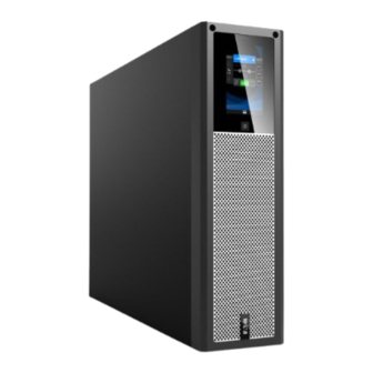
- Page 1 Eaton 9SX 15-20KPM(AU) Series Online UPS...
- Page 2 Copyright © 2020 EATON All rights reserved.
- Page 3 Safety Instructions • SAVE THESE INSTRUCTIONS. See installation instructions before connecting to the supply. This manual contains important instructions that should be followed during installation and maintenance of the UPS and batteries. • In the event of a fire, please use a dry powder fire extinguisher to extinguish the fire.
- Page 4 Personnel Safety RISK OF VOLTAGE BACKFEED. This system has its own power source (the ⚫ battery). Isolate the UPS and check for hazardous voltage upstream and downstream during lockout-tagout operation. Terminal blocks may be energized even if the system is disconnected from the AC power source. Dangerous voltage levels are present within the system.
- Page 5 basic insulation requirements for pollution degree 2). Disconnection and overcurrent protection devices shall be provided by others ⚫ for permanently connected AC input (Normal AC / Bypass AC) and AC output circuits. Check that the indications on the rating plate correspond to your AC powered ⚫...
-
Page 6: Table Of Contents
Contents 1. Introduction ....................6 1.1 Environmental protection ............... 6 1.2 Electronic equipment protection ........... 7 2. Presentation ....................9 2.1 UPS Power Module:................9 2.2 EBM (External Battery Module): ..........10 2.3 MBP (Maintenance Bypass module): ......... 11 3. Mechanical installation ................14 3.1 Unpacking and inspection ............ -
Page 7: Introduction
12V batteries, connected with a neutral point. This can be changed to take 32 blocks of batteries with a neutral point, only to be done by certified Eaton technicians, and the use of the correct battery pack. The charging current is adjustable from 1A to 13A. -
Page 8: Electronic Equipment Protection
Sacks and bags are made of polyethylene. • Packaging materials are recyclable and bear the appropriate identification • symbol Number in Materials Abbreviations the symbols Polyethylene terephthalate High-density polyethylene HDPE Polyvinyl chloride Low-density polyethylene LDPE Polypropylene Polystyrene Follow all local regulations for the disposal of packaging materials. Product The product is made up of recyclable materials. - Page 9 Standard communication options: one RS232 communication port, one ⚫ USB communication port, one dry in port and dry out port. Optional connectivity cards with enhanced communication capabilities. ⚫ Easy, field upgradable firmware. ⚫ Eaton 9SX 15-20KPMAU Dimension: UPS: Model name Size W*H*D(mm) N.W.(kg) Note 9SX 15KPM(AU) 438*129 (3U) *559 24.8...
-
Page 10: Presentation
Maintenance ByPass (MBP): N.W. (kg) Note Model name W*H*D(mm) MBP20K 438*129 (3U) *465 12.8 single MBP (Basic version) single MBP MBP20KPDU 438*129 (3U) *465 13.6 (Standard version) 1+1 parallel MBP MBP20KPARA 438*129 (3U) *465 19.9 (Standard version) Note: 1. Default is setting with the mode:3-1(single source). 2. -
Page 11: Ebm (External Battery Module)
Rear view Note: 1. Parallel port 7. RJ45 port (Modbus/BMS) 2. Dry in/out port 8. DIP switch 3. EPO port 9. Comms. card slot 4. RJ45 port (Detect EBM / MBP) 10. Battery terminal ports 5. USB port 11. Input/output/bypass 6. -
Page 12: Mbp (Maintenance Bypass Module)
Rear view Note: 1. Fuse box 2. Battery port 1 3. Battery port 2 4. RJ45 port (Detect EBM) 5. Ground screw 2.3 MBP (Maintenance Bypass module): Front view Note: 1. Ventilation area 2. Maintenance Bypass label Single MBP (basic version): ⚫... - Page 13 Front view (Remove the front panel) Rear view Note: 1. RJ45 ports (Detect EBM / MBP) 2. AC input terminal ports 3. AC output segment 1(Not programmable) 4. UPS ports 5. Input switch 6. Maintenance bypass switch ⚫ Single MBP (standard version): Front view (Remove the front panel)
- Page 14 Rear view Note: 1. RJ45 ports (Detect EBM / MBP) 2. AC input terminal ports 3. AC output segment 1(Not programmable) 4. AC output segment 2 (Programmable) 5. UPS ports 6. Load 1 with IEC output sockets (Not programmable) 7. Load 2 with IEC output sockets (Programmable) 8.
-
Page 15: Mechanical Installation
Rear view Note: 1. RJ45 ports (Detect EBM / MBP) 2. AC input terminal ports 3. AC output segment 1 (Not programmable) 4. AC output segment 2 (Programmable) 5. UPS1 ports 6. UPS2 ports 7. Input switch 8. Maintenance bypass switch 3. - Page 16 3.1.1 Unpacking the Unit UPS module: EBM (External Battery Module): MBP (Maintenance Bypass module):...
- Page 17 3.1.2 Inspecting accessories • UPS module: UPS accessories 9SX 15-20KPMAU √ USB cable RS232 cable √ Parallel cable (including locker) Copper bus-bar √ (including jumper cable) √ Tower foot √ Rack ear Rack rail kit √ End-user License Agreement √ User manual √...
-
Page 18: Mechanical Installation
3.3 Mechanical installation 1. This series supports two installation modes: Tower installation and rack installation. 2. Leave at least 500mm of clearance for the front and rear of the module for ventilation. 3. Do not carry the module by the front/rear panel during installation. 3.3.1 UPS module installation Rack mount: •... - Page 19 Install the mounting ears. Lock the left/right mounting ears into the UPS with 8pcs M4 flat screws (take note of the mounting ears sides and orientation with the diagram below). Note: There are 2 possible mounting positions for the mounting ears to suit different depth requirements.
- Page 20 • Tower mount: Fasten the pedestal feet to the module by its sides, paying attention to the module’s orientation, the LCD of themodule should be at the top (shown below). With the gravity sensing feature, the LCD screen automatically rotates to the correct orientation based on how the module is reployed.
- Page 21 • Tower mount: 1. Place the EBM modules on the right side of the UPS and align with the front panel of the UPS module. 2. Fasten the pedestal feet: one to the side of the UPS, and the other to the side of the EBM (see diagram below).
-
Page 22: Cable Connections
3.3.3 MBP (Maintenance Bypass Module) installation: MBP module installation steps are the same as UPS, please refer details in the MBP user manual. 4. Cable Connections This chapter outlines the wiring steps for AC input/output to the UPS in different modes, as well as UPS connection to the EBMs Before any connections, ensure that upstream circuit breakers and backfeed contactors are in place to avoid power backfeed to the utility. -
Page 23: Input/Output Wiring
Three phase system 4.1 Input/Output wiring Attention! The current rating of the utility power switch must be greater than that of the UPS input current. Please refer to the following table for the UPS wiring (cross-section of conductor, unit: mm²) Input Output Battery... - Page 24 Note: 1. For single input connection, please select the larger conductor size cross- section. 2. UPS output cable length is recommended not to exceed 10m. 3. UPS default input/output phase mode is: mode 3-1(single source). 4. If the load in a 3-phase output mode is unbalanced, the L wire of the bypass and output may exceed the rated current by 1.732 times.
- Page 25 Recommended output circuit breaker current specifications: Model name Output mode Breaker current 1 phase output 100A 9SX 15KPM(AU) 3 phase output 1 phase output 125A 9SX 20KPM(AU) 3 phase output Note: The diameter and cross-section of the cable conductor depend on the rated power of the UPS.
- Page 26 Item Quantity (PC) Figure Copper busbar Jumper cable 4.1.1. Mode 3-1 (single source) (Default UPS wiring mode) 1. Input: connect the ground cable (PE) to the chassis first 2. Bridge the ‘UPS input terminal N/N’ with ‘busbar #1’, then connect AC cable(N);...
- Page 27 4. Output: connect the ground cable (PE) to the chassis first; 5. Bridge the ‘UPS output terminal N/N’ with ‘busbar #1’, then connect AC cable(N) 6. bridge the ‘UPS output terminal L1/L2/L3’ with ‘busbar #2’, then connect AC cable(L) 4.1.2. Mode 3-1 (dual source) 1.
- Page 28 7. Bridge the ‘UPS output terminal L1/L2/L3’ with ‘busbar #2’, then connect AC cable (L) 4.1.3. Mode 3-3 (single source) 1. Input: connect the main ground cable (PE) to the chassis first 2. Bridge the ‘UPS input terminal N/N’ with ‘busbar #1’, then connect AC cable(N);connect the ‘UPS input terminal L1/L2/L3’...
- Page 29 4.1.4. Mode 3-3 (dual source) 1. Input: connect the main ground cable (PE) to the chassis first 2. Bridge the ‘UPS input terminal N/N’ with ‘busbar #1’, then connect the AC main source cable (N) and bypass source cable(N) with the lugs on top of each other 3.
- Page 30 4.1.5. Mode 1-1 (single source) 1. Input: connect the main ground cable (PE) to the chassis first 2. Bridge the ‘UPS input terminal N/N’ with ‘busbar #1’, then connect the AC cable(N) 3. Fix the ‘jumper cables’ to the ‘UPS input terminal L1/L2/L3’ and ‘busbar #2’, then bridge the ‘UPS bypass terminal L1/L2/L3’...
- Page 31 4.1.6. Mode 1-1 (dual source) 1. Input: connect the main ground cable (PE) to the chassis first 2. Bridge the ‘UPS input terminal N/N’ with ‘busbar #1’, then connect the AC main source cable (N) and bypass source cable (N) with the lugs on top of each other 3.
- Page 32 4.1.7. Mode 1-3(single source) 1. Input: connect the main ground cable (PE) to the chassis first 2. Bridge the ‘UPS input terminal N/N’ with ‘busbar #1’, then connect the AC cable(N) 3. Fix the ‘jumper cable’ to ‘busbar #2’, then bridge the ‘UPS input terminal L1/L2/L3’...
- Page 33 4.1.8. Mode 1-3(dual source) 1. Input: connect the main ground cable (PE) to the chassis first 2. Bridge the ‘UPS input terminal N/N’ with ‘busbar #1’, then connect the AC main source cable (N) and bypass source cable (N) with the lugs on top of each other 3.
-
Page 34: External Battery Module (Ebm) Connection
4.2 External battery module (EBM) Connection The external battery module (EBM) is optional and needs to be purchased separate to the power module. A minimum of 1 pair of EBMs is required for the system to have any stored energy to provide autonomy to your application. - Page 35 • The UPS can be connected to up to 6 strings of batteries, each string contains 2 x EBMs (batt+/batt-). • For EBM connection, only the removal of the TB box’s top cover is neccesarry. Removal of the entire TB box is not required.
-
Page 36: Single Mbp Connection
Note: If the UPS is connected to other types of battery modules (User’s own battery modules), please follow wiring- diagram as above and chapter (table of UPS wiring) to select the cable size for battery connection. 4.3 Single MBP Connection The MBP is an optional module that when used with the UPS, allows the UPS to be . -
Page 37: Paralleled Ups Installation
should be less than 20%. If the distance between the load and the paralleled system is greater than 20 meters, the length difference between the UPS-to-UPS interconnecting lines should be less than 5%. Professional installation is required, please deploy the paralleled system in the restricted area! 5.1 Paralleled UPS installation In the paralleled system, the installation of the UPS modules are the same as single... -
Page 38: Wiring
5.2 wiring Cable-selection table for the paralleled system AC IN and AC OUT : Paralleled system installed by 15KVA UPS (conductor cross-section, unit: mm²) Main Bypass Output input input Mode number 2 UPS 3 UPS... - Page 39 Parallel system installed by 20KVA UPS (conductor cross-section, unit: mm²) Bypass Main input Output input Mode number 2 UPS 3 UPS Note: 1. For single input connection, please select the larger conductor size cross-section. 2. If the load in a 3-phase output mode is unbalanced, the L wire of the bypass and output may exceed the rated current by 1.732 times.
- Page 40 To reduce the risk of parallel system damage: Please use the configured ‘parallel cable’ included as the UPS accessory! After tightening the ‘parallel cables’, secure them with the ‘parallel cable locker’ (as shown below) to prevent accidental disconnection.
- Page 41 5.2.2 Paralleled UPS with independent battery banks Refer to the following illustration for modules placement paralleled system with independent battery bank. 2. Please refer to chapter 4.2 for the wiring method of each UPS and its own EBM.
- Page 42 5.2.3 Paralleled UPS with common battery bank It is possible to configure a paralleled system with common batteries (user’s own batteries). Please refer to the following illustration for this type of connection. 5.2.4 ‘1+1 Parallel MBP’ connection The optional ‘1 + 1 Parallel MBP’ is available to facilitate the connection of 2 paralleled UPS, with maintenance bypass functionality.
-
Page 43: Communication Ports
6. Communication ports Computer ports The UPS provides USB and RS232 communication ports. Please use the communication cables provided as accessories to connect to the corresponding communication port. For RS232 communication, the default parameters are as follows: Baud rate: 2400 •... - Page 44 EPO (Emergency Power Off) The EPO port is located at the rear of the UPS panel. This circuit is normally closed by a jumper connected to it supplied with the UPS. If this connector is opened, the UPS will stop the output and enter a fault mode with ‘EPO active’ alarm. To recover to normal operating state, below steps should be taken: •...
- Page 45 For Lithium Ion battery BMS monitoring, switch the SW-1 to the On position. Intelligent Communication Card Slot This slot enables installation of various compatible MS (mini-slot) type communication cards. These are: NETWORK-M2, INDGW-M2, and RELAY-MS cards. Cards are hot-pluggable and hot-swappable. Contact your Eaton representative for the acquisition of these optional cards.
-
Page 46: Operation Interface
7. Operation interface 7.1 Control panel Note: The control panel has two display modes: horizontal and vertical. The following is an example of using horizontal screen. LED indicator Status Description Steady red UPS is in fault mode Flashing red UPS has one ore more active alarms Steady yellow The UPS is in Battery mode Flashing yellow... -
Page 47: Touch Screen
7.2 Touch screen The Eaton 9SX 15-20KPMAU Series is equipped with a 4.3-inch 65K true color touch screen. This provides a comprehensive graphical menu with UPS information displayed for convenience. 7.2.1 User Interface overview Start animation and Main page Menu and Submenu... - Page 48 This password grants you access to everything under the root menu, it is important to retain it amongst personnels that require this access. Password protection can be disabled under Settings > Password. Contact your Eaton service representative if the password is forgotten/misplaced.
- Page 49 The time setting defines the time stamp on all UPS logs and information. For accurate troubleshooting in the future, the time should be set correctly. Set the desired output voltage based on the critical load’s requirement. 7.2.3 The main page and pop-up page...
- Page 50 Number Name Description Any fault or alarm messages are displayed here. The display will scroll through multiple messages if there ① Alarm or fault are more than one. This section will be left blank when no active alarms are present. Three input status are displayed: Bypass, Mains, and ②...
-
Page 51: Operation
screen where it was left off. • Under any page, the LCD will go back to the main page within 15 minutes of inactivity. • The Screensaver function can be disabled from the Setting page. 7.3 Operation 7.3.1 Query UPS real-time parameters On the Menu page, click the on the Meters icon to enter the real-time parameter page. - Page 52 6.3.2 Query or clear UPS history Click on the history icon on the menu page to enter the history page: The events and alarm list are time stamped to when they occurred, up to 100 entries. Severity levels are distinguised by the different icon colour. Under the Clear menu, tap on the Clear button to clear all records.
- Page 53 7.3.3 UPS operation control Select Control from the Menu page to enter the Control page. This page requires the user password by default. If the password is entered incorrectly for 3 consecutive times within 5 minutes, the LCD will switch back to the main page. Following this, the Control and Setting will be locked for 5 minutes and will not be able to be operated during this timePassword protection can be disabled under: Setting →...
- Page 54 7.3.4 UPS Setting Under the Main Menu page, select Setting to enter the Setting page. This page requires you to enter the user password by default. If you enter the password incorrectly for 3 consecutive times within 5 minutes, the LCD will switch back to the main page.
- Page 55 [High Efficiency] [Frequency] Output Voltage [220V] [230V] [240V] Output Frequency [Auto Detection] [50Hz] [60Hz] ESS Function [Enabled] [Disable] Auto Bypass [Enabled] [Disable] Auto Restart [Enabled] [Disable] Clear SC Fault [Enabled] [Disable] Overload Prealarm [50%,105%] DC Start [Enabled] [Disable] Battery Auto Test [Every ABM Cycle][ Disable] Deep Discharge protection [Enabled] [Disable]...
- Page 56 EBM charge current setting table EBM Str Setting charge Battery number/AH Total AH number current 1 Str EBM 1*2*20 PCS/9AH 2 Str EBM 2*2*20 PCS/9AH 18AH 3 Str EBM 3*2*20 PCS/9AH 27AH 4 Str EBM 4*2*20 PCS/9AH 36AH 5 Str EBM 5*2*20 PCS/9AH 45AH 6 Str EBM...
-
Page 57: Ups Operation
• Connect to the utility power; • The fan will start to rotate, and the LCD displays “EATON” on the Startup animation, then enters the main page; • If UPS ‘start on Bypass’ is enabled, the main page will show that the UPS is in bypass mode;... - Page 58 After the UPS is powered off again, insert the EPO terminal and power it on again • Press the button for more than 1 second, the buzzer will beep and the UPS will start up. After a few seconds, the UPS will enter the mains page.
- Page 59 mode without interruption to the output. • In battery mode, the buzzer will beep once every 4 seconds to indicate that batteries are being discharged. To disable this alarm, see section 7.3.4 Setting → General • Since utility power is not present, the input out of tolerance alarm will appear on the LCD screen.
- Page 60 the battery reaches the set restart threshold, The UPS will automatically restart. If the restart battery level threshold is set to 0%, the UPS will restart as soon as utility power is restored. • Short circuit fault clearance function If the Short circuit fault clearance function is disabled, after the UPS will turn to fault mode after 200ms of a short circuit occurance, and the output will be switched off until the fault is cleared.
- Page 61 7.4.5 Using common battery bank for a paralleled system This product can be set to share a common battery bank for multiple UPS paralleled together. Please contact your certified Eaton service provider to perform this operation. Ensure the battery capacity meets the full load requirement for the parallele system: ...
-
Page 62: Battery Maintenance
shall be greater than 27Ah; 8. Battery maintenance Batteries are an important component in a UPS system. The life span of the batteries is dependant on the ambient temperature and the number of discharges. A general rule of thumb is: The higher the temperature is past the rated ambient temperature, and higher the number of discharges that occurs, the lower the life span of the batteries will be. -
Page 63: Troubleshooting
9. Troubleshooting The following table is a list of faults with descriptions. If presented on the screen, contact your Eaton service representative to provide the following information: 1. Product model, serial number; 2. Fault date; 3. Description of the fault... - Page 64 Bus imbalance Bus imbalance Please contact your supplier Bus short Bus short Please contact your supplier Bus soft start failed Bus boost fault Please contact your supplier Output short Turn off the UPS, remove all L1 Output short loads, verify the load is not Output short L2 Output short fault or short circuit.
- Page 65 Parallel connection is Please check if the connection Parallel line loss abnormal is normal Please check parallel setting, if Parallel setting Parallel inconsistent still alarm, Please contact your inconsistent supplier...
-
Page 66: Appendix: General Specification
10. Appendix: General specification Model name 15KPM(AU) 20KPM(AU) Rated power 15kVA/15kW 20kVA/20kW Rated frequency 50/60Hz Voltage range (Phase Voltage) Input 100~300VAC Rated voltage 220/230/240VAC (Phase Voltage) 35A(3phase) 43A(3phase) Rated current 105A(1phase) 129A(1phase) Frequency 40-70Hz Charging current 1~13A adjustable (default 2A) Rated voltage 220/230/240VAC (Phase Voltage) - Page 67 Battery Number 2*16-2*20PCS adjustable (default 2*16PCS) Environment Ambient temperature 0℃ ~ 50℃(Derating 50% above 40°C) Relative humidity 0 ~ 95%(no condensing) Operating altitude <4000m(Derating use above1km) Storage temperature -15℃ ~ 40℃ (With Batteries) Storage temperature -25℃ ~ 60℃ (Without Batteries) Certification Safety EN62040-1:2008+A1:2013...
- Page 68 614-40045-00...
Need help?
Do you have a question about the 9SX 15KPM Serie and is the answer not in the manual?
Questions and answers