Table of Contents
Advertisement
Advertisement
Table of Contents

Related Manuals for Eaton 9SX 6000VA


Summary of Contents for Eaton 9SX 6000VA
- Page 1 ИНСТРУКЦИЯ Eaton 9SX 6000VA RT3U (9104-12567)
- Page 2 9SX 5000 9SX 6000 9PX 5000 9PX 6000 9SX EBM 180V 9PX EBM 180V Installation and user manual Copyright © 2013 EATON All rights reserved. Service and support: Call your local service representative 5-6kVA EU_EN...
- Page 3 SAFETY INSTRUCTIONS SAVE THESE INSTRUCTIONS. This manual contains important instructions that should be followed during installation and maintenance of the UPS and batteries. The 9SX and 9PX models that are covered in this manual are intended for installation in an environment within 0 to 40°C, free of conductive contaminant. This equipment has been tested and found to comply with the limits for a Class A digital device, pursuant to Part 15 of the FCC Rules.
- Page 4 The system is not for use in a computer room AS DEFINED IN the standard for the Protection of Information Technology Equipment, ANSI/NFPA 75 (US installations only). Contact Eaton resellers to order a special battery kit, if needed to meet the ANSI/NFPA 75 require- ment.
- Page 5 During the replacement of the Battery Module, it is imperative to use the same type and number of element as the original Battery Module provided with the UPS to maintain an identical level of performance and safety. In case of doubt, don’t hesitate to contact your EATON representative. •...
-
Page 7: Table Of Contents
Configuring battery settings ..................26 Retrieving the Event log ....................27 Retrieving the Fault log ....................27 6. Communication ................28 Communication ports ....................28 Eaton Intelligent Power Software suite ...............31 7. UPS maintenance ................32 7 .1 Equipment care ......................32 7 .2 Storing the equipment ....................32 7 .3... -
Page 8: Introduction
Then follow the indications in this manual. To discover the entire range of EATON products and the options available for the 9SX and 9PX range, we invite you to visit our web site at www.eaton.com/powerquality or contact your EATON representative. - Page 9 - causing hours of lost productivity and expensive repairs. With the Eaton 9SX and 9PX, you can safely eliminate the effects of power disturbances and guard the integrity of your equipment. Providing outstanding performance and reliability, the Eaton 9SX and 9PX’s unique benefits include: •...
-
Page 10: Presentation
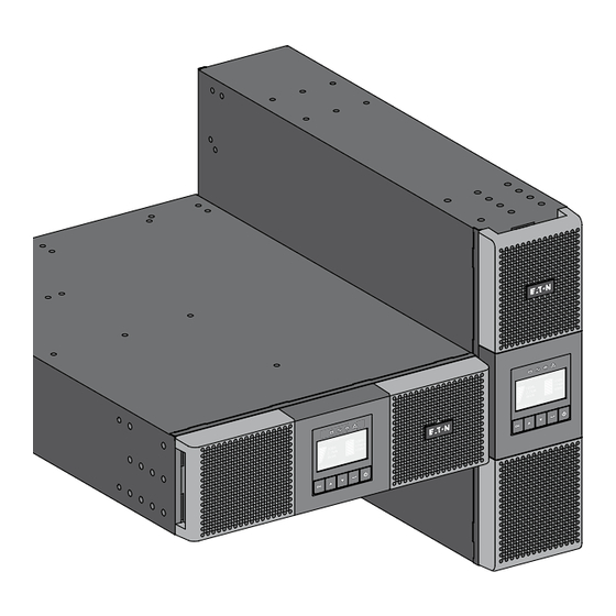
2. Presentation Standard installations Tower installation Rack installation Description Weights Dimensions (inch/mm) (lb/kg) D x W x H 9SX 5000 106 / 48 27.0 x 17.3 x 5.1 / 685 x 440 x 130 9SX 6000 106 / 48 27.0 x 17.3 x 5.1 / 685 x 440 x 130 9PX 5000 106 / 48 27.0 x 17.3 x 5.1 / 685 x 440 x 130... -
Page 11: Rear Panels
2. Presentation Rear panels 9SX 5000 / 6000 RS232 communication port USB communication port Dry (relay) contacts communication port Connector for ROO (Remote On/Off) control Connectors for automatic recognition of an additional battery module Connector for Parallel operation (for 9PX only) Connector for RPO (Remote Power Off) control 9PX 5000 / 6000... -
Page 13: Accessories
2. Presentation Accessories Part number Description 9SXEBM180RT, Extended battery module 9PXEBM180 Rack kit 9PX/9SX Network-MS Network card Network-M2 Modbus-MS Modbus and network card INDGW-MS Relay-MS Relay card INDRELAY-MS MBP6Ki HotSwap MBP 6000i TFMR11Ki Transformer 11000i BINTSYS Battery Integration System EBMCBL180 1.8m cable 180V EBM MBP6Ki Input/Output terminal blocks... -
Page 14: Control Panel
2. Presentation Control panel The UPS has a five-button graphical LCD. It provides useful information about the UPS itself, load status, events, measurements and settings. Online mode Fault indicator (green) indicator (red) Battery mode Bypass mode indicator (orange) indicator (orange) Online mode 100% 2.7kW... -
Page 15: Lcd Description
2. Presentation LCD description After 5 minutes of inactivity, the LCD displays the screen saver. The LCD backlight automatically dims after 10 minutes of inactivity. Press any button to restore the screen. Operation status Online mode 100% Load/equipment status 2.7kW 30min Battery status 3.0kVA... -
Page 16: Display Functions
[Product type/model] / [Part/Serial number] / [UPS/NMC firmware] / [Com card IPv4], [Com card IPv6], [Com card MAC] / [Detected accessories] Register product Links to Eaton registration website User settings The following table displays the options that can be changed by the user. Submenu... - Page 17 2. Presentation Submenu Available settings Default settings Interrupt time If Bypass transfer is enabled, [10ms] Interrupt time: [10ms] [20ms] Define break duration when transfer on Bypass In/Out settings Overload [10%] … [102%] [102%] Load % when overload alarm occurs prealarm Redundancy [Unitary UPS] [Hot Standby] Unitary UPS...
-
Page 19: Installation
3. Installation Inspecting the equipment If any equipment has been damaged during shipment, keep the shipping cartons and packing materials for the carrier or place of purchase and file a claim for shipping damage. If you discover damage after acceptance, file a claim for concealed damage. To file a claim for shipping damage or concealed damage: 1. -
Page 20: Checking The Accessory Kit
3. Installation Checking the accessory kit • Verify that the following additional items are included with the UPS: (2) Tower stands Rack kit for 19-inch enclosures (optional) (2) cable glands for Input/Output connection (2) cable lockers for 16A outlets (2) cable lockers for 10A outlets (2) IEC 10A cables Network communication card (optional, standard on the Netpack versions) -
Page 21: Connecting The Ebm(S)
3. Installation Connecting the EBM(s) A small amount of arcing may occur when connecting an EBM to the UPS. This is normal and will not harm personnel. Insert the EBM cable into the UPS battery connector quickly and firmly. 1. Plug the EBM power cable(s) into the battery connector(s). Up to 6 EBMs may be connected to the UPS. -
Page 22: Tower Installation
3. Installation Tower installation If you ordered other UPS accessories, refer to specific user manuals to check the tower installation with the UPS. To install the cabinet: 1. Place the UPS on a flat, stable surface in its final location. 2. -
Page 23: Rack Installation
3. Installation Rack installation If you ordered other UPS accessories, refer to specific user manuals to check the rack installation with the UPS. • Prepare UPS for rack mounting. This step requires two people. The UPS is heavy. To ease its rack mounting, you can remove the battery pack from the UPS as explained below. - Page 25 3. Installation • Rack mounting of UPS, EBM, and accessory modules. Follow steps 1 to 4 for module mounting on the rails. The rails and necessary hardware are supplied by EATON (optional). Page 20 5-6kVA EU_EN...
-
Page 26: Installation Requirements
3. Installation Installation requirements Recommended protective devices and cable cross-sections 1. Recommended upstream protection UPS power rating Upstream circuit breaker 5000VA D curve – 32A 6000VA D curve – 32A 2 poles circuit breaker to UPS Normal AC source N(L2) G N(L2) L1 Do not use 30 mA RCD/ELCB breaker upstream the UPS. -
Page 27: Installation Depending On The System Earthing Arrangement (Sea)
3. Installation Installation depending on the system earthing arrangement (SEA) Change in SEA between upstream and downstream or galvanic isolation required Main low Isolation voltage transformer switchboard Load (MLVS) Normal AC Isolation Main low transformer voltage switchboard Load (MLVS) Normal AC Page 22 5-6kVA EU_EN... -
Page 28: Power Cables Connection
4. Power cables connection Access to terminal blocks 1. Remove the terminal blocks cover (one screw) 2. Punch the knockouts and insert the cables/conduits inside • High leakage current: Earth connection essential before connecting supply. Input/Output connection This type of connection must be carried out by qualified electrical personnel Before carrying out any connection, check that the upstream protection device (Normal AC source) is open "O"... -
Page 29: Operation
The UPS should be in Online mode. The internal batteries charge to 90% capacity in less than 3 hours. However, Eaton recommends that the batteries charge for 48 hours after installation or long-term storage. Starting the UPS on Battery Before using this feature, the UPS must have been powered by utility power with output enabled at least once. -
Page 31: Operating Modes
5. Operation Operating modes The Eaton 9SX and 9PX front panel indicates the UPS status through the UPS indicators, see page 13. Online mode During Online mode, the indicator illuminates solid and the UPS is powered from the utility. The UPS monitors and charges the batteries as needed and provides filtered power protection to your equipment. -
Page 32: Setting High Efficiency Mode
Bypass voltage monitoring: if Bypass quality is not in tolerance, then the UPS will remain in Online mode. Eaton recommends to use the HE mode only to protect I/T equipment. To set the High Efficiency mode: 1. Put the UPS on Bypass: press any button to activate the menu options, select Control and Go to Bypass. -
Page 33: Retrieving The Event Log
5. Operation Retrieving the Event log To retrieve the Event log through the display: 1. Press any button to activate the menu options, then select Event log. 2. Scroll through the listed events. Retrieving the Fault log To retrieve the Fault log through the display: 1. -
Page 34: Communication
RS232 or USB communication port on the UPS. The UPS can now communicate with EATON power management software. • Relay output contacts The UPS incorporates four relay outputs; each information is available with a close or open contact. n.c. - Page 35 6. Communication • Remote On/Off Remote On/Off allows remote action of button to switch On/Off the UPS. Normally open When contact changes from open to closed, the UPS is switched-on (or stays On). When contact changes from closed to open, the UPS is switched-off (or stays Off). On/Off control via button has priority over the remote control.
- Page 37 6. Communication Remote control connection and test 1. Check the UPS is shut down and the electrical supply network disconnected. 2. Remove RPO connector from the UPS by unfitting the screws. 3. Connect a normally closed volt-free contact between the two pins of connector. Contact open: shut down of UPS To return to normal operation, deactivate the external remote shut down contact and restart the UPS from the front panel.
-
Page 38: Eaton Intelligent Power Software Suite
It also gives you a complete record of critical power events, and it notifies you of important UPS or power information. If there is a power outage and the 9SX and 9PX UPS battery power becomes low, Eaton Software suite can automatically shut down your computer system to protect your data before the UPS shutdown occurs. -
Page 39: Ups Maintenance
If you store the equipment for a long period, recharge the battery every 6 months by connecting the UPS to utility power. The internal batteries charge to 90% capacity in less than 3 hours. However, Eaton recommends that the batteries charge for 48 hours after long-term storage. Check the battery recharge date on the shipping carton label. -
Page 40: Replacing Batteries
7. UPS maintenance Replacing batteries DO NOT DISCONNECT the batteries while the UPS is in Battery mode. Batteries can be replaced easily without turning off the UPS or disconnecting the load. If you prefer to remove input power to change the batteries, see "UPS Shutdown" on page 24. Consider all warnings, cautions, and notes before replacing batteries. - Page 41 7. UPS maintenance • Replacing the internal battery The internal battery is heavy. Use caution when handling the heavy batteries. To replace the battery pack: 1. Remove the center cover of the front panel 2. Remove the two screws to open the left side of the front panel 3.
- Page 43 7. UPS maintenance • Replacing the EBM(s) The EBM is heavy. Lifting the cabinet into a rack requires a minimum of two people. To replace the EBM(s): 1. Unplug the EBM power cable and battery detection cable from the UPS. If additional EBM(s) are installed, unplug the EBM power cable and battery detection cable from each EBM.
-
Page 44: Replacing The Ups Equipped With A Hotswap Mbp
7. UPS maintenance Replacing the UPS equipped with a HotSwap MBP The HotSwap MBP allows to service or replace the UPS without interrupting the connected loads. Refer to the specific user manual for more information about HotSwap MBP . To remove the UPS: 1. -
Page 45: Troubleshooting
8. Troubleshooting The Eaton 9PX and 9SX are designed for durable, automatic operation and also alert you whenever poten- tial operating problems may occur. Usually the alarms shown by the control panel do not mean that the output power is affected. Instead, they are preventive alarms intended to alert the user. - Page 46 8. Troubleshooting UPS overtemperature The UPS internal temperature is If the UPS transferred to Bypass too high or a fan has failed. mode, the UPS will return to normal operation when the temperature drops At the warning level, the UPS 5°C below the warning level.
-
Page 47: Silencing The Alarm
8. Troubleshooting Silencing the alarm Press the ESC (Escape) button on the front panel display to silence the alarm. Check the alarm condition and perform the applicable action to resolve the condition. If the alarm status changes, the alarm beeps again, overriding the previous alarm silencing. -
Page 49: Specifications
9. Specifications Model specifications Table 1. Power Module model list Model Power ratings 9SX5KiRT 5000VA / 4500W 9PX5Ki 5000VA / 4500W 9SX6KiRT 6000VA / 5400W 9PX6Ki 6000VA / 5400W Table 2. Extended Battery Module model list Model Configuration Battery voltage For power ratings 9SXEBM180RT Rack / Tower... - Page 50 9. Specifications Table 6. Electrical output All models Normal mode Battery mode Voltage regulation ±1% ±1% Efficiency > 98% (High Efficiency mode) > 91% > 93% Frequency regulation Sync with line ±5% of nominal line ±0.5% of auto-selected nominal frequency (outside this range: ±0.5% frequency of auto-selected nominal frequency) Nominal output...
- Page 51 9. Specifications CE / C-Tick / cULus Agency markings Operating temperature 0 to 40°C (32 to 104°F) in Online mode, with linear derating for altitude Note: thermal protection switches load to Bypass in case of overheating. 0 to 40°C (32 to 104°F) with batteries Storage temperature -15 to 60°C (5 to 140°F) without batteries Transit temperature...
-
Page 52: Glossary
10. Glossary Bypass AC source Source supplying the bypass line. The equipment can be transferred to the by- pass line if an overload occurs on the UPS output, for maintenance or in the event of a malfunction. Frequency converter Operating mode used to convert the AC-power frequency between the UPS input and output (50Hz ->... - Page 53 Page 44 5-6kVA EU_EN...
- Page 54 СМОТРИТЕ ТАКЖЕ Источники бесперебойного Стабилизаторы Светодиодные Защитные реле питания напряжения прожекторы Промышленные Аккумуляторные Умные датчики Генераторы светильники батареи Портативные зарядные Удлинители станции...
Need help?
Do you have a question about the 9SX 6000VA and is the answer not in the manual?
Questions and answers