Eaton 9155 User Manual
8–15 kva
Hide thumbs
Also See for 9155:
- User manual (90 pages) ,
- Manual (28 pages) ,
- Installation instructions manual (10 pages)
Table of Contents
Advertisement
Advertisement
Table of Contents

Related Manuals for Eaton 9155


Summary of Contents for Eaton 9155
- Page 1 ® Eaton 9155 UPS 8–15 kVA User's Guide...
- Page 2 Schneider Automation. National Electrical Code and NEC are registered trademarks of National Fire Protection Association, Inc. All other trademarks are property of their respective companies. ECopyright 2004–2011 Eaton Corporation, Raleigh, NC, USA. All rights reserved. No part of this document may be reproduced in any way without the express written approval of Eaton Corporation.
- Page 3 89/336/EEC, Council Directive relating to electromagnetic compatibility 92/31/EEC, Amending Directive 89/336/EEC relating to EMC The EC Declaration of Conformity is available upon request for products with a CE mark. For copies of the EC Declaration of Conformity, contact: Eaton Power Quality Oy Koskelontie 13 FIN-02920 Espoo...
-
Page 4: Special Symbols
Special Symbols The following are examples of symbols used on the UPS or accessories to alert you to important information: RISK OF ELECTRIC SHOCK - Observe the warning associated with the risk of electric shock symbol. CAUTION: REFER TO OPERATOR'S MANUAL - Refer to your operator's manual for additional information, such as important operating and maintenance instructions. -
Page 5: Table Of Contents
..............164201553 Rev G (www.eaton.com/powerquality) Eaton 9155 UPS (8–15 kVA) User's Guide... - Page 6 ..........164201553 Rev G (www.eaton.com/powerquality) Eaton 9155 UPS (8–15 kVA) User's Guide...
-
Page 7: Introduction
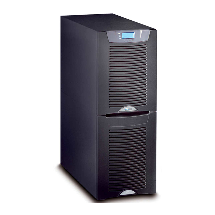
With the Eaton 9155, you can safely eliminate the effects of electrical line disturbances and guard the integrity of your systems and equipment. Figure 1 shows the Eaton 9155 UPS and an optional Extended Battery Module (EBM). - Page 8 (CAN) Bridge Card provides connectivity for system metering and operational mode control. The parallel system consists of two to three UPSs, each with a parallel CAN Bridge Card, and a parallel tie cabinet. Refer to the Eaton 9155 Parallel UPS (8–15 kVA) User's Guide for more information.
-
Page 9: Safety Warnings
Keep unauthorized personnel away from batteries. Proper disposal of batteries is required. Refer to your local codes for disposal requirements. Never dispose of batteries in a fire. Batteries may explode when exposed to flame. 164201553 Rev G (www.eaton.com/powerquality) Eaton 9155 UPS (8–15 kVA) User's Guide... - Page 10 Une mise au rebut réglementaire des batteries est obligatoire. Consulter les règlements en vigueur dans votre localité. Ne jamais jeter les batteries au feu. L'exposition aux flammes risque de les faire exploser. 164201553 Rev G (www.eaton.com/powerquality) Eaton 9155 UPS (8–15 kVA) User's Guide...
-
Page 11: Advertencias De Seguridad
Es necesario desechar las baterías de un modo adecuado. Consulte las normas locales para conocer los requisitos pertinentes. Nunca deseche las baterías en el fuego. Las baterías pueden explotar si se las expone a la llama. 164201553 Rev G (www.eaton.com/powerquality) Eaton 9155 UPS (8–15 kVA) User's Guide... - Page 12 SAFETY WARNINGS 164201553 Rev G (www.eaton.com/powerquality) Eaton 9155 UPS (8–15 kVA) User's Guide...
-
Page 13: Ups Setup
2-High UPS 3-High UPS 2-High UPS with Maintenance Bypass Module (MBM) or Power Distribution Module (PDM) 3-High UPS with MBM/PDM 3-High UPS with Isolation Transformer 2-High EBM 3-High EBM 164201553 Rev G (www.eaton.com/powerquality) Eaton 9155 UPS (8–15 kVA) User's Guide... -
Page 14: Clearances
UPS SETUP Clearances The following clearances are recommended for the Eaton 9155 UPS: From Front of Cabinet 36” (91.4 cm) working space From Back of Cabinet 6” (15.2 cm) without an MBM/PDM installed; with an MBM/PDM installed, clearance is determined by the customer-supplied mating... - Page 15 Figure 3. Removing the Brackets and Shipping Pad Reinstall the front cover removed in Step 3. Hang the top edge of the cover on the cabinet first, then lower the bottom edge and snap into place. 164201553 Rev G (www.eaton.com/powerquality) Eaton 9155 UPS (8–15 kVA) User's Guide...
- Page 16 Figure 4. Unloading the Cabinet With the cabinet supported, slowly pull the pallet away from the cabinet (see Figure 5). Figure 5. Removing the Pallet Roll the cabinet to the desired location. 164201553 Rev G (www.eaton.com/powerquality) Eaton 9155 UPS (8–15 kVA) User's Guide...
-
Page 17: Selecting An Installation Option
UPS SETUP Selecting an Installation Option You are now ready to install the Eaton 9155 UPS. Select one of the following installation options according to your UPS configuration: UPS Configuration Installation Chapter UPS only Chapter 4, “UPS Only Installation” on page 13 UPS with an optional input isolation Chapter 5, “Input Isolation Transformer Installation”... - Page 18 UPS SETUP 164201553 Rev G (www.eaton.com/powerquality) Eaton 9155 UPS (8–15 kVA) User's Guide...
-
Page 19: Ups Only Installation
NOTE To accommodate the feature of easy system expandability, it is recommended that initial installation of the Eaton 9155 UPS contain wiring to support the maximum capacity of the UPS cabinet. Switch off utility power to the distribution point where the UPS will be connected. - Page 20 See Table 1 for specifications and Figure 7 for a detailed view of the UPS terminal block. Replace the UPS wiring access cover. Continue to “Stabilizing the Cabinet” on page 43 to complete the UPS installation. 164201553 Rev G (www.eaton.com/powerquality) Eaton 9155 UPS (8–15 kVA) User's Guide...
-
Page 21: Ups Terminal Block Wiring
AWG size than shown in this table because of temperature, number of conductors in the conduit, or long service runs. Follow local requirements. 2 2A Input Output Figure 7. UPS Terminal Block 164201553 Rev G (www.eaton.com/powerquality) Eaton 9155 UPS (8–15 kVA) User's Guide... - Page 22 UPS ONLY INSTALLATION Figure 8. UPS Only Wiring Diagram 164201553 Rev G (www.eaton.com/powerquality) Eaton 9155 UPS (8–15 kVA) User's Guide...
-
Page 23: Input Isolation Transformer Installation
NOTE To accommodate the feature of easy system expandability, it is recommended that initial installation of the Eaton 9155 UPS contain wiring to support the maximum capacity of the UPS cabinet. Switch off utility power to the distribution point where the UPS will be connected. - Page 24 11. Hardwire the input, output, and ground terminations for the input isolation transformer. See Table 2 for specifications and Figure 10 for a detailed view of the input isolation transformer terminal block. 164201553 Rev G (www.eaton.com/powerquality) Eaton 9155 UPS (8–15 kVA) User's Guide...
- Page 25 * Use only 75°C-rated copper wire. Minimum wire size is based on 120/208 full load ratings applied to NEC Code Table 310‐16. Code may require a larger AWG size than shown in this table because of temperature, number of conductors in the conduit, or long service runs. Follow local requirements. 164201553 Rev G (www.eaton.com/powerquality) Eaton 9155 UPS (8–15 kVA) User's Guide...
- Page 26 Greenlee punch or similar device (see Figure 10 on page 19). 16. Install the supplied edge grommet in the top of the input isolation transformer wiring cover. 164201553 Rev G (www.eaton.com/powerquality) Eaton 9155 UPS (8–15 kVA) User's Guide...
- Page 27 18. Punch a hole in the bottom of the MBM/PDM using a Greenlee punch or similar device for wiring access. Insert the supplied nylon bushing inside the wiring access hole. 19. Continue to the following chapter, “UPS-Mounted Bypass Switch Installation,” to complete the installation. 164201553 Rev G (www.eaton.com/powerquality) Eaton 9155 UPS (8–15 kVA) User's Guide...
- Page 28 INPUT ISOLATION TRANSFORMER INSTALLATION Figure 12. UPS with Input Isolation Transformer Wiring Diagram 164201553 Rev G (www.eaton.com/powerquality) Eaton 9155 UPS (8–15 kVA) User's Guide...
- Page 29 INPUT ISOLATION TRANSFORMER INSTALLATION Figure 13. UPS with Input Isolation Transformer and MBM/PDM Wiring Diagram 164201553 Rev G (www.eaton.com/powerquality) Eaton 9155 UPS (8–15 kVA) User's Guide...
- Page 30 INPUT ISOLATION TRANSFORMER INSTALLATION 164201553 Rev G (www.eaton.com/powerquality) Eaton 9155 UPS (8–15 kVA) User's Guide...
-
Page 31: Ups-Mounted Bypass Switch Installation
Remove the lowest top cover screw on each side of the UPS and discard. Lowest Top Cover Screw (one each side) Connecting Plate (8 screws) Figure 14. UPS Rear View (2-High Cabinet Shown) 164201553 Rev G (www.eaton.com/powerquality) Eaton 9155 UPS (8–15 kVA) User's Guide... - Page 32 UPS electronics unit through an access slot. UPS Electronics Unit MBM/PDM Wiring Access Cover Conduit Landing Plates Figure 16. Installing the MBM or PDM (MBM Shown) 164201553 Rev G (www.eaton.com/powerquality) Eaton 9155 UPS (8–15 kVA) User's Guide...
- Page 33 Step 1. Continue to the following section, “Wiring the MBM/PDM.” Screws for Top of Module Screws to L-Bracket (three each side) Figure 17. Securing the MBM or PDM (MBM Shown) 164201553 Rev G (www.eaton.com/powerquality) Eaton 9155 UPS (8–15 kVA) User's Guide...
-
Page 34: Wiring The Mbm/Pdm
NOTE To accommodate the feature of easy system expandability, it is recommended that initial installation of the Eaton 9155 UPS contain wiring to support the maximum capacity of the UPS cabinet. Switch off utility power to the distribution point where the UPS will be connected. - Page 35 Hardwire the input, output, and ground terminations for the MBM/PDM. See Table 4 for specifications and Figure 19 for a detailed view of the MBM/PDM terminal block. TB10 Figure 19. MBM/PDM Hardwiring (PDM Shown) 164201553 Rev G (www.eaton.com/powerquality) Eaton 9155 UPS (8–15 kVA) User's Guide...
- Page 36 Connect the maintenance bypass (red and black) wires to TB1-2 (the A/B maintenance bypass auxiliary contacts) on the UPS terminal block. Input Output A/B Maintenance Bypass Auxiliary Contacts Figure 20. Wiring from Maintenance Bypass Switch to UPS 164201553 Rev G (www.eaton.com/powerquality) Eaton 9155 UPS (8–15 kVA) User's Guide...
- Page 37 Replace the wiring access cover on the UPS and the optional isolation transformer, if applicable. 10. Replace the MBM/PDM wiring access cover and conduit landing plate. 11. Continue to “Stabilizing the Cabinet” on page 43 to complete the installation. 164201553 Rev G (www.eaton.com/powerquality) Eaton 9155 UPS (8–15 kVA) User's Guide...
- Page 38 UPS-MOUNTED BYPASS SWITCH INSTALLATION Figure 21. UPS with MBM Wiring Diagram 164201553 Rev G (www.eaton.com/powerquality) Eaton 9155 UPS (8–15 kVA) User's Guide...
- Page 39 UPS-MOUNTED BYPASS SWITCH INSTALLATION Figure 22. UPS with PDM Wiring Diagram 164201553 Rev G (www.eaton.com/powerquality) Eaton 9155 UPS (8–15 kVA) User's Guide...
- Page 40 UPS-MOUNTED BYPASS SWITCH INSTALLATION 164201553 Rev G (www.eaton.com/powerquality) Eaton 9155 UPS (8–15 kVA) User's Guide...
-
Page 41: Wall-Mounted Bypass Switch Installation
21.0” (53.4 cm) Width 14.0” (35.6 cm) Depth 6.8” (17.2 cm) Mounting 11.0” (28.0 cm) Centers 20.0” (50.8 cm) Weight 31 lb (14.1 kg) Figure 23. Wall-Mounted Bypass Switch Dimensions 164201553 Rev G (www.eaton.com/powerquality) Eaton 9155 UPS (8–15 kVA) User's Guide... -
Page 42: Wall-Mounted Bypass Switch Setup
Remove the six screws from the bypass switch front cover and remove the cover (see Figure 24). Remove and discard any packing material from inside the bypass switch. 164201553 Rev G (www.eaton.com/powerquality) Eaton 9155 UPS (8–15 kVA) User's Guide... -
Page 43: Wiring The Wall-Mounted Bypass Switch
NOTE To accommodate the feature of easy system expandability, it is recommended that initial installation of the Eaton 9155 UPS contain wiring to support the maximum capacity of the UPS cabinet. Switch off utility power to the distribution point where the bypass switch cabinet and UPS will be connected. - Page 44 See Figure 26 for a detailed view of the terminal strip label. Figure 26. Wall-Mounted Bypass Switch Terminal Strip Wiring 164201553 Rev G (www.eaton.com/powerquality) Eaton 9155 UPS (8–15 kVA) User's Guide...
- Page 45 AWG size than shown in this table because of temperature, number of conductors in the conduit, or long service runs. Follow local requirements. 2 2A Input Output Figure 27. UPS Terminal Block 164201553 Rev G (www.eaton.com/powerquality) Eaton 9155 UPS (8–15 kVA) User's Guide...
- Page 46 Do Not Connect Red and Black Wires To UPS Terminal Block Signal Cable Figure 28. Signal Cable Installation 11. Replace the bypass switch front cover and the UPS wiring access cover. 164201553 Rev G (www.eaton.com/powerquality) Eaton 9155 UPS (8–15 kVA) User's Guide...
- Page 47 WALL-MOUNTED BYPASS SWITCH INSTALLATION Figure 29. UPS with Wall-Mounted Bypass Switch Wiring Diagram 164201553 Rev G (www.eaton.com/powerquality) Eaton 9155 UPS (8–15 kVA) User's Guide...
- Page 48 WALL-MOUNTED BYPASS SWITCH INSTALLATION 164201553 Rev G (www.eaton.com/powerquality) Eaton 9155 UPS (8–15 kVA) User's Guide...
-
Page 49: Stabilizing The Cabinet
Chapter 8 Stabilizing the Cabinet NOTE For seismic installations, you MUST order and install an Eaton 9155 UPS seismic kit; do not use the following instructions. NOTE For non-seismic installations, you MUST install the stabilizing bracket on all 3-high cabinets. The stabilizing bracket is optional for 2-high cabinets. - Page 50 STABILIZING THE CABINET M4 Screws Figure 31. Stabilizing Bracket with One Cabinet M4 Screws Figure 32. Stabilizing Bracket with Two Cabinets 164201553 Rev G (www.eaton.com/powerquality) Eaton 9155 UPS (8–15 kVA) User's Guide...
- Page 51 STABILIZING THE CABINET M4 Screws Figure 33. Stabilizing Bracket with Three Cabinets 164201553 Rev G (www.eaton.com/powerquality) Eaton 9155 UPS (8–15 kVA) User's Guide...
- Page 52 STABILIZING THE CABINET 164201553 Rev G (www.eaton.com/powerquality) Eaton 9155 UPS (8–15 kVA) User's Guide...
-
Page 53: Extended Battery Module Installation
EBM. Repeat for each additional EBM. EBM Battery Circuit Breaker Rear Ground Strap EBM Battery Connector UPS Battery Connector UPS Battery Circuit Breaker Cable Figure 34. Typical EBM Installation (2-High Cabinets Shown) 164201553 Rev G (www.eaton.com/powerquality) Eaton 9155 UPS (8–15 kVA) User's Guide... - Page 54 NOTE After UPS startup, ensure maximum battery runtime by configuring the UPS for the correct number of EBMs (see page 64). Front Ground Strap Figure 35. Front Ground Strap Installation (2-High Cabinets Shown) 164201553 Rev G (www.eaton.com/powerquality) Eaton 9155 UPS (8–15 kVA) User's Guide...
-
Page 55: Communication
Signal Input 1 X-Slot Communication Bay #2 Signal Input 2 REPO (normally open) REPO (normally closed) DB-9 Communication Port Relay Output Contacts Figure 36. Communication Options and Control Terminals 164201553 Rev G (www.eaton.com/powerquality) Eaton 9155 UPS (8–15 kVA) User's Guide... -
Page 56: Installing Communication Options And Control Terminals
With wire cutters, cut either side of the tab and twist down to remove the tab (see Figure 39). 164201553 Rev G (www.eaton.com/powerquality) Eaton 9155 UPS (8–15 kVA) User's Guide... - Page 57 Be sure the cables fit in the access holes in the covers. Continue to “Operation” on page 57 to start up the UPS. Figure 40. Reinstalling the Front Covers 164201553 Rev G (www.eaton.com/powerquality) Eaton 9155 UPS (8–15 kVA) User's Guide...
-
Page 58: Communication Options
COMMUNICATION Communication Options The Eaton 9155 has serial communication capabilities through the DB-9 communication port or through an X-Slot card in one of the available bays. In addition, the LanSafe Power Management Software can be installed and used to communicate with the UPS via one of the serial communication connections. -
Page 59: X-Slot Cards
USB Card - connects to a USB port on your computer. NOTE The Eaton 9155 does not detect plug-and-play hardware. Before installing the USB Card, set the UPS baud rate to 1200 through the front panel (see Table 9 on page 59). -
Page 60: Lansafe Power Management Software
COMMUNICATION LanSafe Power Management Software Each Eaton 9155 UPS ships with LanSafe Power Management Software and an interface cable. To begin installing LanSafe software, see the instructions accompanying the Software Suite CD. NOTE Use only the supplied communication cable to connect the UPS to your computer. -
Page 61: Remote Emergency Power-Off
The relay output contacts must not be connected to any utility connected circuits. Reinforced insulation to the utility is required. The relay output contacts have a maximum rating of 30 Vac/1A and 60 Vdc/2A nominal values. 164201553 Rev G (www.eaton.com/powerquality) Eaton 9155 UPS (8–15 kVA) User's Guide... -
Page 62: Programmable Signal Inputs
If active, the UPS knows that input is fed from the generator. Bypass is disabled; the automatic battery test is disabled. External Transformer This option is not used. Overtemperature 164201553 Rev G (www.eaton.com/powerquality) Eaton 9155 UPS (8–15 kVA) User's Guide... -
Page 63: Operation
Chapter 11 Operation This chapter contains information on how to use the Eaton 9155, including front panel operation, UPS startup and shutdown, operation of the maintenance bypass switch, and configuring the UPS for Extended Battery Modules (EBMs). Control Panel Functions The UPS has a four-button graphical LCD with backlight. -
Page 64: Changing The Language
Display Functions As the default or after 15 minutes of inactivity, the LCD displays the selectable startup screen. The default is the Eaton logo and can be changed to the Mimic screen in the User Settings menu. The backlit LCD automatically dims after a long period of inactivity. Press any button to restore the screen. -
Page 65: User Settings
(see “Programmable Signal Inputs” on page 56) Serial Port Config Port: [X-Slot-1] [X-Slot-2/Serv] 19200 Speed: [19200] [9600] [2400] [1200] Parallel Operation Settings Refer to the Eaton 9155 Parallel UPS (8–15 kVA) User's Guide. Modem Config Modem Installation <Not Installed> Set Modem Call Events Event #0... - Page 66 1 through 65535 seconds 120s Site Wiring Fault Notice Enabled/Disabled Enabled Reset Custom Event Settings 0 through 32 Total: 0/32 Auto Output Configuration Enabled/Disabled Enabled for initial startup Disabled after initial startup 164201553 Rev G (www.eaton.com/powerquality) Eaton 9155 UPS (8–15 kVA) User's Guide...
-
Page 67: Ups Startup
UPS with an optional wall-mounted bypass switch “Wall-Mounted Maintenance Bypass Startup” on page 64 Parallel UPS configuration Refer to the Eaton 9155 Parallel UPS (8–15 kVA) User's Guide Normal Mode Startup To start up the UPS: If you have an optional MBM/PDM or wall-mounted bypass switch, verify that the maintenance bypass switch is in the UPS position (see Figure 45 on page 68 or Figure 48 on page 72). -
Page 68: Starting The Ups On Battery
Confirm the selection. Press and hold the button for three seconds, until the UPS stops beeping. The UPS starts in Battery mode within two minutes and supplies battery power to your equipment. 164201553 Rev G (www.eaton.com/powerquality) Eaton 9155 UPS (8–15 kVA) User's Guide... -
Page 69: Internal Bypass Startup
Switch on utility power where the UPS is connected. The load is now powered by utility power. To transfer the load to the UPS, see “Using the UPS-Mounted Maintenance Bypass Switch” on page 68. 164201553 Rev G (www.eaton.com/powerquality) Eaton 9155 UPS (8–15 kVA) User's Guide... -
Page 70: Wall-Mounted Maintenance Bypass Startup
* UPS-32 models contain 2 strings; EBM-64 models contain 4 strings. UPS-64 models contain 4 strings; EBM-96 models contain 6 strings. Press the button to save the setting. Press the button until the Eaton logo appears. 164201553 Rev G (www.eaton.com/powerquality) Eaton 9155 UPS (8–15 kVA) User's Guide... -
Page 71: Ups Shutdown
Switch the UPS battery circuit breaker to the OFF position. The UPS is disconnected from the batteries and is on logic power only. Switch off utility power where the UPS is connected. 164201553 Rev G (www.eaton.com/powerquality) Eaton 9155 UPS (8–15 kVA) User's Guide... - Page 72 OPERATION 164201553 Rev G (www.eaton.com/powerquality) Eaton 9155 UPS (8–15 kVA) User's Guide...
-
Page 73: Ups Maintenance
Check the battery recharge date on the shipping carton label. If the date has expired and the batteries were never recharged, do not use the UPS. Contact your service representative. 164201553 Rev G (www.eaton.com/powerquality) Eaton 9155 UPS (8–15 kVA) User's Guide... -
Page 74: When To Replace Batteries
The UPS-mounted maintenance bypass switch is part of the optional Maintenance Bypass Module (MBM) or Power Distribution Module (PDM) and is located on the back of the UPS (see Figure 45). Figure 45. Maintenance Bypass Switch (PDM Shown) 164201553 Rev G (www.eaton.com/powerquality) Eaton 9155 UPS (8–15 kVA) User's Guide... - Page 75 Figure 46 shows a UPS with a separate battery cabinet and a UPS-mounted bypass switch. UPS-Mounted Bypass Switch Bypass User-Supplied Service Building Load Service Distribution Panel Panel Bypass Service Bypass Service Figure 46. Typical Hardwired Installation with UPS-Mounted Bypass Switch 164201553 Rev G (www.eaton.com/powerquality) Eaton 9155 UPS (8–15 kVA) User's Guide...
-
Page 76: Using The Wall-Mounted Bypass Switch
UPS, this is the appropriate position for UPS maintenance or repair. Disconnects the load from the UPS output power and AC input power, as well as AC input power to the UPS input. 164201553 Rev G (www.eaton.com/powerquality) Eaton 9155 UPS (8–15 kVA) User's Guide... - Page 77 Figure 47 shows a UPS with a separate battery cabinet and a wall-mounted bypass switch. Wall-Mounted Bypass Switch Service Line Building Load Service Distribution Panel Panel Service Line Service Line User-Supplied Figure 47. Typical Hardwired Installation with Wall-Mounted Bypass Switch 164201553 Rev G (www.eaton.com/powerquality) Eaton 9155 UPS (8–15 kVA) User's Guide...
- Page 78 Step 3; otherwise, power to the load may be lost. Turn the maintenance bypass switch to the UPS position to return to Normal mode. The UPS is now powering the load. 164201553 Rev G (www.eaton.com/powerquality) Eaton 9155 UPS (8–15 kVA) User's Guide...
-
Page 79: Specifications
3-high: UPS with one battery & one input isolation transformer section PW9155-15-64 3-high: UPS with two battery sections 15 kVA, 13.5 kW Extended Battery Description Module (EBM) PW9155-EBM-64 2-high: two battery sections PW9155-EBM-96 3-high: three battery sections 164201553 Rev G (www.eaton.com/powerquality) Eaton 9155 UPS (8–15 kVA) User's Guide... - Page 80 NOM-019-SCFI, UL 1778, CSA C22.2, No. 107.3; EN 55022 Class A (CISPR22 Class A) and IEC 60950; IEC 62040-1-1 Agency Markings cULus, cUL, CE, NOM-NYCE EMC (Class A) IEC 62040-2, FCC Part 15, ICES-003, VCCI 164201553 Rev G (www.eaton.com/powerquality) Eaton 9155 UPS (8–15 kVA) User's Guide...
- Page 81 Output Peak Current Efficiency (Minimum) Power Dissipation (BTU/hr) 5582 5582 5582 5582 5582 DC Voltage (Supply) * Input current for the input isolation transformer is 4% higher than for the UPS. 164201553 Rev G (www.eaton.com/powerquality) Eaton 9155 UPS (8–15 kVA) User's Guide...
- Page 82 Output Peak Current Efficiency (Minimum) Power Dissipation (BTU/hr) 3300 3300 3300 3300 3300 DC Voltage (Supply) * Input current for the input isolation transformer is 4% higher than for the UPS. 164201553 Rev G (www.eaton.com/powerquality) Eaton 9155 UPS (8–15 kVA) User's Guide...
-
Page 83: Battery Specifications
+3 EBM-96 Batteries 15 kVA/13.5 kW 12 kVA/10.8 kW 10 kVA/9 kW 8 kVA/7.2 kW NOTE Battery times are approximate and vary depending on the load configuration and battery charge. 164201553 Rev G (www.eaton.com/powerquality) Eaton 9155 UPS (8–15 kVA) User's Guide... - Page 84 SPECIFICATIONS 164201553 Rev G (www.eaton.com/powerquality) Eaton 9155 UPS (8–15 kVA) User's Guide...
-
Page 85: Troubleshooting
UPS position (or restart the UPS if you do not have a switch). If the condition persists, contact your service representative. Battery test failed The batteries need service. Contact your service representative. 164201553 Rev G (www.eaton.com/powerquality) Eaton 9155 UPS (8–15 kVA) User's Guide... -
Page 86: Silencing The Alarm
Please have the following information ready when you call for service: Model number Serial number Firmware version number Date of failure or problem Symptoms of failure or problem Customer return address and contact information 164201553 Rev G (www.eaton.com/powerquality) Eaton 9155 UPS (8–15 kVA) User's Guide... -
Page 87: Warranty
3.1 kVA ® WARRANTOR: The warrantor for the limited warranties set forth herein is Eaton Corporation Inc. or its subsidiaries and affiliates. Corporation, an Ohio Corporation company (“Company”). LIMITED WARRANTY: This limited warranty (this “Warranty”) applies only to the original End-User (the “End-User”) of any Eaton 9120, 9125, 9130, 9135, 9140, and FERRUPS up to 3.1 kVA Products (individually and collectively, the “Product”) purchased on or after June 1, 2004, and... -
Page 88: Load Protection Guarantee (Us And Canada)
This load protection guaranty (this “Guaranty”) applies only to the original End-User (the “End-User”) of any Eaton 3105, 5110, 5115, 5125, 5130, 9120, 9125, 9130, 9135, 9140, 9150, 9155, 9170+, and FERRUPS Products (individually and collectively, the “Product”) and cannot be transferred. This Guaranty applies even in the event that the Product is initially sold by Company for resale to an End-User. - Page 89 TO MAKE A CLAIM: In the USA, call the Customer Reliability Center 7x24 at 800-356-5737. Outside of the USA, contact your local Eaton product sales or service representative. For comments or questions about this Load Protection Guaranty, write to the Customer Quality Representative, 3301 Spring Forest Road, Raleigh, North Carolina 27616 USA.
- Page 90 WARRANTY 164201553 Rev G (www.eaton.com/powerquality) Eaton 9155 UPS (8–15 kVA) User's Guide...
- Page 92 *164201553G* 164201553 G...
Need help?
Do you have a question about the 9155 and is the answer not in the manual?
Questions and answers
Alarm disconnect battery 199 cause
The "Disconnect Battery" alarm in the Eaton 9155 is caused when the UPS does not recognize the battery, which may occur if the battery circuit breaker is not in the correct position. The action to resolve this is to verify that the battery circuit breaker is in the proper position.
This answer is automatically generated