Table of Contents
Advertisement
Quick Links
MANUFACTURED BY:
CEDAR COVE
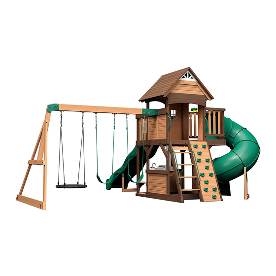
Wooden Swing Set
Backyard Discovery
3305 Airport Drive
Pittsburg, KS 66762
Model # 2001053
Owner's Manual & Assembly Instructions
800-856-4445
WARNING
NOT SUITABLE FOR
CHILDREN UNDER 36
MONTHS. SMALL PARTS.
average 2 person assembly time
average tube slide assembly time
assembly time may vary based on skill level
For the most up to date assembly manual,
to register your set, or to order replacement parts please visit
www.backyarddiscovery.com
SAVE THIS ASSEMBLY MANUAL FOR FUTURE REFERENCE IN THE EVENT THAT
YOU NEED TO ORDER REPLACEMENT PARTS.
Made in China | INS-2001053-A-CEDAR COVE-ENG 11-25-19
Advertisement
Table of Contents

Related Manuals for Backyard Discovery CEDAR COVE 2001053


Summary of Contents for Backyard Discovery CEDAR COVE 2001053
- Page 1 MANUFACTURED BY: CEDAR COVE Wooden Swing Set Backyard Discovery 3305 Airport Drive Pittsburg, KS 66762 Model # 2001053 Owner's Manual & Assembly Instructions 800-856-4445 WARNING NOT SUITABLE FOR CHILDREN UNDER 36 MONTHS. SMALL PARTS. average 2 person assembly time average tube slide assembly time...
- Page 2 INSTALLATION SERVICES AVAILABLE! Need a helping hand? Let our team of professionals handle the installation for you! *Installation services are only available to U.S. customers. With Go Configure, we bring you 18 years of experience right to your doorstep. We service a wide array of indoor and outdoor recreation products that most consumers don’t have the time or ability to deliver &...
- Page 3 Owner’s Manual Please Read This Before Starting Assembly MISSING A PART? CALL US BEFORE GOING BACK TO THE STORE Th e store where you made your purchase does not stock parts for this item. If you have assembly questions or you are missing or have damaged parts, please call 1-800-856-4445 you can also visit www.backyarddiscovery.com...
- Page 4 Botanical, Adventure Playsets, and Leisure Time Products. Backyard Discovery warrants that this product is free from defect in materials and workmanship for a period of one (1) year from the original date of purchase. Th is one (1) year warranty covers all parts including wood, hardware, and accessories. All wood carries a fi ve (5) year pro-rated warranty against rot and decay. Refer to the schedule below for charges associated with replacement of parts under this Limited Warranty.
- Page 5 Owner’s Manual Operating Instructions and Safety Warnings WARNING: BURN HAZARD • Pay special attention to plastic and metal surfaces as they may be hot enough to cause burns. • Always check the temperature of the product before NOTE: letting your children play on it. •...
- Page 6 Owner’s Manual Please Read This Before Starting Assembly Positioning Your Playcenter Suggested Playground Surfacing • Th e playcenter is designed to be installed on a level • Do not install home playground equipment over surface by an adult with an adult helper. Place concrete, asphalt, packed earth, grass, carpet, or any in a fl at area of your yard to minimize ground other hard surface.
- Page 7 Owner’s Manual Please Read This Before Starting Assembly APPENDIX A The following information is from the United States X3.1.3.2 Do not install loose-fi ll surfacing over hard surfaces such as concrete or asphalt. Consumer Product Safety Commission’s Information X3.1.4 Poured-In-Place Surfaces or Pre-Manufactured Sheet for playground surfacing material;...
- Page 8 • Check all moving parts including swing seats, Backyard Discovery assumes no responsibility or ropes, cables, and chains for wear, rust, or other liability for any charge incurred by the Customer for deterioration.
- Page 9 About Our Wood Backyard Discovery uses 100% Cedar (C. Lanceolata) wood. Although we take great care in selecting the best quality lumber available, wood is still a product of nature and susceptible to weathering which can change the appearance of your set.
- Page 10 Owner’s Manual Assembly Tips Protrusion Hazard Incorrect Correct If you see exposed threads and your bolt protrudes beyond the T-Nut you may have over tightened the bolt or used incorrect hardware. If you’ve overtightened, remove the bolt and add washers to eliminate the protrusion.
- Page 11 Owner’s Manual Assembly Tips ASSEMBLY TIP: Keep an eye out for these boxes which will contain helpful pictures and information making the assembly process as quick and painless as possible. Sorting Wood When removing the wood from the boxes we recommend arranging them by part number before you begin assembly.
- Page 12 Owner's Manual Tools Required for Installation...
- Page 13 Owner's Manual Basic Setup Dimensions & Assembly Notes Place the set on level ground, not less than 6'-7" [2 m] from any structure or obstruction such as a fence, garage, house, overhanging branches, laundry lines, or electrical wires. • While assembling unit, take time before and after each phase to make sure fort is level. If fort is not level, assembly will be difficult and improper assembly may result.
- Page 14 Owner's Manual Parts Identification Wood Components (Not to Scale) SWING BEAM - W4L13335 3 3/8"x5 1/4"x89 1/2" (86x134x2274) (x1) SB 9" BLOCK - W4L13337 3 3/8"x5 1/4"x9" (86x134x228) (x1) UPRIGHT - W4L13166 1 3/8"x3 3/8"x51 3/4" (36x86x1314) (x1) UPRIGHT - W4L13167 1 3/8"x3 3/8"x51 3/4"...
- Page 15 Owner's Manual Parts Identification Wood Components (Not to Scale) LEFT UPRIGHT - W4L13322 1 3/8"x3 3/8"x56 3/4" (36x86x1441) (x1) MIDDLE UPRIGHT - W4L13323 1 3/8"x3 3/8"x56 3/4" (36x86x1441) (x1) RIGHT UPRIGHT - W4L13327 1 3/8"x3 3/8"x56 3/4" (36x86x1441) (x1) END SUPPORT - W4L13208 1 7/16"x3 3/8"x49 1/4"...
- Page 16 Owner's Manual Parts Identification Wood Components (Not to Scale) ATTACHMENT BOARD - W4L13326 1"x3 3/8"x40 1/2" (24x86x1030) (x1) UPRIGHT - W4L13338 (x2) 1"x2 3/4"x55 7/8" (24x70x1419) DECK BRACE - W4L13202 DECK BRACE - W4L13205 LADDER RUNG - W4L13324 (x2) 1"x3 3/8"x15 3/4" (24x86x400) (x2) 1"x3 3/8"x15 3/4"...
- Page 17 Owner's Manual Parts Identification Wood Components (Not to Scale) GROUND BOARD - W4L13164 GROUND BOARD - W4L13165 5/8"x5 1/4"x40 1/2" (16x134x1030) 5/8"x5 1/4"x40 1/2" (16x134x1030) (x1) (x1) WALL RAIL - W4L13169 5/8"x5 1/4"x63" (16x134x1601) (x1) ARCHED WALL RAIL - W4L13190 WALL RAIL - W4L13172 5/8"x5 1/4"x40 1/2"...
- Page 18 Owner's Manual Parts Identification Wood Components (Not to Scale) FLOOR BOARD - W4L07597 WALL RAIL - W4L13311 5/8"x3 3/8"x21 1/8" (16x86x537) (x9) 5/8"x3 3/8"x41 1/4" (16x86x1048) (x1) FLOOR BOARD - W4L13305 COUNTER TOP BOARD - W4L13318 FLOOR BOARD - W4L13304 5/8"x3 1/8"x19 7/8"...
- Page 19 Owner's Manual Parts Identification Wood Components (Not to Scale) WALL PANEL - W2A02840 WALL PANEL - W2A02841 1"x20 3/8"x37 3/4" (24x517x956) (x1) 1"x20 3/8"x37 3/4" (24x517x858) (x1) WALL PANEL - W2A02849 1"x16 7/8"x24 5/8" (24x430x627) (x2) WALL PANEL - W2A02088 WALL PANEL - W2A02089 1"x16 7/8"x46 1/2"...
- Page 20 Owner's Manual Parts Identification Wood Components (Not to Scale) REAR UPRIGHT - W2A02660 1 3/8"x3 3/8"x51 3/4" (36x86x2074) (x1) GABEL PANEL - W2A02842 1 1/8"x16 3/8"x53 1/2" (27x414x1359) (x2) ROOF PANEL - W2A02092 1 3/8"x48"x19 3/8" (35x1220x491) (x2) ROOF PANEL - W2A02093 1 3/8"x48"x19 1/8"...
- Page 21 Owner's Manual Parts Identification Hardware Components H100363 BOLT WH BLK (x1) 5/16X6 H100415 BOLT WH BLK H100396 BOLT WH BLK (x2) (x3) 5/16x3 3/4 5/16x1/2 H100663 BOLT WH BLK H100503 BOLT WH BLK (x4) 5/16x3/4 (x4) 5/16x3-1/2 H100416 BOLT WH BLK H100468 BOLT WH BLK (x13)
- Page 22 Owner's Manual Parts Identification Hardware Components H100831 NUT BARREL H100206 LAG SCREW WH BLK H100193 NUT BARREL PTH BLK (x4) (x2) 5/16x3 (x2) WH BLK 1/4x3/4 5/16x1-1/2 H100399 NUT BARREL H100197 LAG SCREW WH BLK H100192 NUT BARREL WH BLK (x1) (x1) 5/16x2 1/2...
- Page 23 Owner's Manual Parts Identification Hardware Components H100090 SCREW PFH H100821 SCREW PFH BLK H100380 SCREW PFH BLK (x41) 8x2 1/2" (x1) 8x2-3/4 (x12) 8x1 1/8 H100111 H100201 SCREW PFH SCREW PFH BLK H100387 SCREW PFH BLK (x4) (x17) 8x2-1/2 (x45) 8x1-1/4 H100089 SCREW PFH...
- Page 24 Owner's Manual Parts Identification Accessory Components (Not to Scale) A100041 TORX WRENCH (x2) T-40 H100114 TORX WRENCH (x2) T-30 A100042 TORX BIT H100147 TORX BIT H100764 SCREW SETTER (x2) (x2) T-40 T-30 (x1) SLIDE SUPPORT A100034 (x4) TUBE 9198036 CHALK BOARD A6P00324 TUBE SLIDE (x1)
- Page 25 Owner's Manual Parts Identification Accessory Components (Not to Scale) HAND GRIP A100134 HAND GRIP A100118 (x2) GREEN 816 C/C METAL GREEN (x2) 381 c/c A100178 AUGER GROUND A100314 "A" REVISION BYD ID TAG (x6) STAKE A100164 (x1) (LARGE) AGES (x1) 3-10 A100322 PLASTIC...
- Page 26 Owner's Manual Parts Identification Accessory Components (Not to Scale) A6P00096 Telescope GREEN HC ROCK A6P00037 (x1) (x12) A6P00282 BBQ GRILL (x1) A4M01126 WEB SWING (x1) 141154 GRILL FOOD SET (x1) A6P00397 SWING (x2) BE SURE TO WASH ALL PLASTIC TOYS BEFORE USE.
- Page 27 LADDER STEP 1 LEFT UPRIGHT - W4L13322 1 3/8"x3 3/8"x56 3/4" (36x86x1441) (x1) H100201 SCREW PFH BLK (x8) 8x2-1/2 LADDER RUNG - W4L13324 1"x3 3/8"x19 1/4" (24x86x489) (x4) (x8) SCREW - 2 1/2" (x1) LEFT UPRIGHT (x4) LADDER RUNG...
- Page 28 LADDER STEP 2 H100201 SCREW PFH BLK MIDDLE UPRIGHT - W4L13323 (x8) 8x2-1/2 1 3/8"x3 3/8"x56 3/4" (36x86x1441) (x1) (x1) MIDDLE UPRIGHT (x8) SCREW - 2 1/2"...
- Page 29 LADDER STEP 3 H100200 SCREW PFH BLK REAR SUPPORT - W4L13325 (x4) 8x1 1/2 5/8"x3 3/8"x21 1/4" (16x86x541) (x1) (x1) REAR SUPPORT (x4) SCREW - 1 1/2" 1 7/8 in [48 mm]...
- Page 30 LADDER STEP 4 H100391 SCREW PFH BLK RIGHT UPRIGHT - W4L13327 (x3) 1 3/8"x3 3/8"x56 3/4" (36x86x1441) (x1) H100379 T-NUT BLK ATTACHMENT BOARD - W4L13326 (x4) 5/16 1"x3 3/8"x40 1/2" (24x86x1030) (x1) ASSEMBLY NOTE: ADD T-NUTS AS SHOWN (x2) PRIOR TO INSTALLING THE T-NUT - 5/16"...
- Page 31 FORT ASSEMBLY STEP 5 H100391 SCREW PFH BLK UPRIGHT - W4L13338 (x10) 1"x2 3/4"x55 7/8" (24x70x1419) (x2) (x10) SCREW - 2" (x2) UPRIGHT FLUSH BACK SIDE FLUSH ENDS...
- Page 32 LADDER STEP 6 ROCK BOARD - W4L13331 ROCK BOARD - W4L13328 H100398 T-NUT BLK 5/8"x1 3/4"x17 7/8" (16x46x453) 5/8"x3 3/8"x17 7/8" (16x86x453) (x1) (x8) (x24) ROCK BOARD - W4L13329 ROCK BOARD - W4L13330 5/8"x3 3/8"x17 7/8" (16x86x453) 5/8"x3 3/8"x17 7/8" (16x86x453) (x4) (x4) H100200...
- Page 33 LADDER STEP 7 H100380 SCREW PFH BLK ROCKWALL CLEAT - W4L13332 (x11) 8x1 1/8 5/8"x2 3/8"x53 7/8" (16x60x1370) (x1) CENTER CLEAT ON BACK & ATTACH (x11) SCREW - 1 1/8" (x1) ROCKWALL CLEAT...
- Page 34 LADDER STEP 8 H100489 BOLT PTH BLK H100473 WASHER LOCK INT BLK A6P00037 GREEN HC ROCK #2 (x24) 1/4x3/4 (x24) 8x15 (x12) (x24) BOLT - 3/4" (x24) WASHER - 8x15" ARROW FACES UPWARD (x12) GREEN HC ROCK #2...
- Page 35 LADDER STEP 9 H100503 BOLT WH BLK (x4) 5/16x3-1/2 A100134 HAND GRIP GREEN 816 C/C (x2) H100379 T-NUT BLK (x4) 5/16 (x4) BOLT - 3 1/2" (x4) T-NUT - 5/16" (x2) HAND GRIP GREEN 816 C/C...
- Page 36 SLIDE ASSEMBLY STEP 1 SLIDE BED SUPPORT - W100935 (x1) 5/8"x3 3/8"x19 7/8" (16x86x505) A6P00385 SLIDE BED 10' DARK GREEN (x1) H100115 H100074 BOLT WH T-NUT (x3) 5/16x1/2 (x3) 5/16 (x1) SLIDE BED 10' DARK GREEN TIP: SEE SLIDE ASSEMBLY INSTALLATION STEP FOR DECK MOUNTING HOLE DRILLING LOCATIONS.
- Page 37 SLIDE ASSEMBLY STEP 2 53" SLIDE A4M01117 A100031 A100033 (x1) BRACE (RIGHT) SLIDE RAIL 10' BOTTOM RIGHT GREEN SLIDE RAIL 10' TOP RIGHT GREEN (x1) (x1) 53" SLIDE A100030 A100032 A4M01118 SLIDE RAIL 10' BOTTOM LEFT GREEN SLIDE RAIL 10' TOP LEFT GREEN (x1) BRACE (LEFT) (x1)
- Page 38 SLIDE ASSEMBLY STEP 3 A100034 SLIDE SUPPORT TUBE (x4) NOTE: PLACE (1) SLIDE RAIL ASSEMBLY ON A FLAT SURFACE AND BEGIN INSERTING SLIDE BED AT THE BOTTOM OF THE SLIDE RAIL (FIG. 1). HAVE A HELPER BEND THE SLIDE BED TOWARDS THE TOP OF THE SLIDE AND INSERT THE BED INTO THE SLIDE CAVITY.
- Page 39 SLIDE ASSEMBLY STEP 4 H100090 SCREW PFH (x38) 8x2 1/2" NOTE: ONCE THE SLIDE BED, SUPPORT TUBES, AND SUPPORT BOARD ARE COMPLETELY IN THE CAVITY AND SUPPORT POCKET, SECURE USING 2-1/2" SCREWS AT EACH OF THE PILOT HOLE LOCATIONS AS SHOWN. REPEAT PROCESS FOR OPPOSITE SLIDE RAIL.
- Page 40 SLIDE ASSEMBLY STEP 5 SLIDE BRACE WIDE - W4L13300 H100008 BOLT WH H100074 T-NUT (x1) 1"x3 3/8"x18 3/4" (24x86x476) (x8) 5/16x1 (x8) 5/16 H100111 SCREW PFH (x4) SLIDE BRACE - W4L13333 1"x3 3/8"x20 1/8" (24x86x512) (x2) (x1) 111 (x4) SCREW - 2" (x1) (x1) 074 (x8)
- Page 41 SWING BEAM STEP 1 ASSEMBLY SWING BEAM - W4L13335 3 3/8"x5 1/4"x89 1/2" (86x134x2274) (x1) SWING BEAM SWING BEAM A100325 A100326 EXTENSION EXTENSION (x1) (x1) BRACKET-RIGHT BRACKET-LEFT SB 9" BLOCK - W4L13337 (x1) 3 3/8"x5 1/4"x9" (86x134x228) A4M00993 EXTENDED SWING H100416 H100192 NUT BARREL WH...
- Page 42 SWING BEAM STEP 2 ASSEMBLY H100654 BOLT HEX H100107 WASHER LOCK (x12) 3/8x5-1/2 H100073 T-NUT H100102 WASHER FLAT (x12) (x12) (x12) 11x25 10x18 H100543 SCREW PFH SD A100164 BYD ID PLATE 2011 (x4) 8x1/2 ASSEMBLY A4M00505 (x1) SWING HANGER (x6) (x4) SCREW - 1/2"...
- Page 43 SWING BEAM STEP 3 ASSEMBLY END SUPPORT - W4L13208 ANGLE BRACE - W4L13206 1 7/16"x3 3/8"x49 1/4" (36x86x1251) (x1) 1 7/16"x3 3/8"x80 1/2" (36x86x2045) (x2) SP50 SWING BEAM SUPPORT - W4L13336 GROUND BOARD - W4L13207 (x1) 3 3/8"x3 3/8"x49 3/8" (86x86x1254) 15/16"x5 1/4"x87 3/4"...
- Page 44 SWING BEAM STEP 4 ASSEMBLY (x1) SWING BEAM ASSEMBLY H100416 BOLT WH BLK H100192 NUT BARREL WH (x2) 5/16x3 (x2) 5/16x7/8 (x1) END FRAME ASSEMBLY NOTE: INSTALL HARDWARE, THEN TIGHTEN ALL HARDWARE NOW. (x2) NUT BARREL - 7/8" (x2) BOLT - 3"...
- Page 45 FORT ASSEMBLY STEP 1 ARCHED WALL RAIL - W4L13192 H100457 BOLT WH BLK (x1) 5/8"x5 1/4"x40 5/8" (16x134x1032) (x4) 5/16x2 H100379 T-NUT BLK (x4) 5/16 H100198 WASHER LOCK UPRIGHT - W4L13185 UPRIGHT - W4L13183 (x4) EXT BLK 1 3/8"x3 3/8"x16 1/8" (36x86x411) (x1) (x1) 1 3/8"x3 3/8"x16 1/8"...
- Page 46 FORT ASSEMBLY STEP 2 UPRIGHT - W4L13168 1 3/8"x3 3/8"x81 5/8" (36x86x2074) H100459 BOLT WH BLK (x1) H100457 BOLT WH BLK (x4) (x14) 5/16x2 5/16x1 1/4 REAR UPRIGHT - W2A02660 1 3/8"x3 3/8"x51 3/4" (36x86x2074) (x1) H100128 SCREW PWH (x2) 8x5/8 H100198 WASHER LOCK...
- Page 47 FORT ASSEMBLY STEP 3 H100205 BOLT WH BLK (x1) FROM STEP 1 (x4) 5/16x2-1/4 H100379 T-NUT BLK (x8) 5/16 H100198 WASHER LOCK EXT BLK (x4) SWING BEAM MOUNT - W4L13186 8x19 (x1) 1"x5 1/4"x62 1/8" (24x134x1577) (x1) FROM STEP 2 (x8) T-NUT - 5/16"...
- Page 48 FORT ASSEMBLY STEP 4 UPRIGHT - W4L13166 H100457 BOLT WH BLK GROUND BOARD - W4L13163 1 3/8"x3 3/8"x51 3/4" (36x86x1314) (x1) (x12) 5/16x2 5/8"x5 1/4"x64 11/16" (16x134x1644) (x1) UPRIGHT - W4L13167 1 3/8"x3 3/8"x51 3/4" (36x86x1314) (x1) H100198 WASHER LOCK WALL RAIL - W4L13172 (x12) EXT BLK...
- Page 49 FORT ASSEMBLY STEP 5 WALL RAIL - W4L13170 (x1) 1"x5 1/4"x61 3/8" (24x134x1560) H100206 LAG SCREW WH BLK H100458 LAG SCREW WH BLK (x2) 5/16x3 (x2) 5/16x2 ANGLED WALL RAIL - W4L13195 GROUND BOARD - W4L13165 5/8"x5 1/4"x45 3/4" (16x134x1162) 5/8"x5 1/4"x40 1/2"...
- Page 50 FORT ASSEMBLY STEP 6 GROUND BOARD - W4L13164 H100458 LAG SCREW WH BLK WALL RAIL - W4L13171 5/8"x5 1/4"x40 1/2" (16x134x1030) (x4) 5/16x2 1"x5 1/4"x61 3/8" (24x134x1560) (x1) (x1) H100198 WASHER LOCK (x16) EXT BLK 8x19 ANGLED WALL RAIL - W4L13194 ARCHED WALL RAIL - W4L13190 H100471 LAG SCREW WH BLK...
- Page 51 FORT ASSEMBLY STEP 7 BALCONY UPRIGHT - W4L13180 1 3/8"x2 3/8"x34 5/8" (36x60x881) (x2) H100458 LAG SCREW WH BLK H100198 WASHER LOCK (x12) 5/16x2 (x12) EXT BLK 8x19 WALL RAIL - W4L13204 WALL RAIL - W4L13188 (x2) 1"x2 3/8"x22 1/4" (24x60x566) 1"x2 3/8"x23 1/4"...
- Page 52 FORT ASSEMBLY STEP 8 H100205 BOLT WH BLK WALL BOARD - W4L13181 (x6) 5/16x2-1/4 H100379 1"x5 1/4"x42 1/2" (24x134x1080) T-NUT BLK (x1) (x6) 5/16 H100198 WASHER LOCK WALL RAIL - W4L13191 (x6) EXT BLK 1"x2 3/8"x40 5/8" (24x60x1032) (x1) 8x19 (x1) WALL RAIL (x6)
- Page 53 FORT ASSEMBLY STEP 9 H100378 BOLT WH BLK H100198 WASHER LOCK (x2) 5/16x1 3/4 H100379 T-NUT BLK EXT BLK (x2) (x2) DECK BRACE - W4L13202 5/16 8x19 1"x3 3/8"x15 3/4" (24x86x400) (x2) H100405 WASHER LOCK H100487 LAG SCREW WH BLK EXT BLK (x2) (x2)
- Page 54 FORT ASSEMBLY STEP 1 0 WALL RAIL - W4L13173 5/8"x5 1/4"x20 1/2" (16x134x521) (x1) H100457 BOLT WH BLK H100469 NUT BARREL H100396 BOLT WH BLK PORCH GROUND BOARD - W4L13176 WH BLK (x2) 5/16x2 (x1) (x1) 5/16x1/2 5/8"x2 3/8"x21 1/8" (16x60x537) (x2) 5/16x5/8 WALL RAIL - W4L13189...
- Page 55 FORT ASSEMBLY STEP 1 1 UPRIGHT - W4L13175 H100457 BOLT WH BLK H100198 WASHER LOCK (x1) 1 3/8"x3 3/8"x80 3/4" (36x86x2052) (x10) 5/16x2 EXT BLK (x10) 8x19 UPRIGHT - W4L13203 H100379 T-NUT BLK (x1) 1 3/8"x3 3/8"x80 3/4" (36x86x2052) (x10) 5/16 (x10) T-NUT - 5/16"...
- Page 56 FORT ASSEMBLY STEP 1 2 H100458 WALL RAIL - W4L13174 LAG SCREW WH BLK (x2) 5/16x2 5/8"x5 1/4"x40 1/2" (16x134x1030) (x1) H100198 WASHER LOCK PORCH GROUND BOARD - W4L13178 (x10) EXT BLK (x1) 1"x2 3/8"x40 1/2" (24x60x1030) 8x19 H100471 LAG SCREW WH BLK ARCHED WALL RAIL - W4L13187 (x8) 5/16x1 1/2...
- Page 57 FORT ASSEMBLY STEP 13 H100407 BOLT WH BLK H100198 WASHER LOCK (x2) 5/16x1 1/2 H100379 T-NUT BLK (x2) EXT BLK (x2) 5/16 8x19 DECK BRACE - W4L13205 (x2) 1"x3 3/8"x15 3/4" (24x86x400) H100405 WASHER LOCK H100487 LAG SCREW WH BLK EXT BLK (x2) (x2)
- Page 58 FORT ASSEMBLY STEP 14 FLOOR JOIST - W4L07602 H100391 SCREW PFH BLK (x1) 1"x2 3/8"x40 1/2" (24x60x1029) (x4) SUPPORT BOARD - W4L07599 H100382 SCREW PFH BLK 1"x1 3/8"x37 5/8" (24x34x957) (x2) (x6) 8x1 3/4 (x1) FLOOR JOIST (x2) (x4) SUPPORT BOARD SCREW - 2"...
- Page 59 FORT ASSEMBLY STEP 15 H100486 H100391 SCREW PFH BLK BOLT WH BLK H100401 BOLT WH BLK FLOOR JOIST - W4L07603 (x2) (x2) 1/4x5/8 (x1) 1/4x1/2 (x1) 1"x2 3/8"x20 1/4" (24x60x513) A4M01110 90° L-BRACKET - (x2) H100382 SCREW PFH BLK SUPPORT BOARD - W4L07601 H100399 NUT BARREL H100398...
- Page 60 FORT ASSEMBLY STEP 16 FLOOR BOARD - W4L13308 5/8"x3 3/8"x40 5/8" (16x86x1031) (x10) H100086 SCREW PFH FLOOR BOARD - W4L13307 (x66) 8x1 1/2 (x1) 5/8"x3 1/8"x40 5/8" (16x78x1031) FLOOR BOARD - W4L13309 5/8"x3 3/8"x40 5/8" (16x86x1031) (x1) NOTE: EVENLY SPACE FLOOR BOARDS (x1) FLOOR BOARD (x1)
- Page 61 FORT ASSEMBLY STEP 17 H100457 BOLT WH BLK (x4) 5/16x2 H100379 T-NUT BLK (x4) 5/16 H100378 BOLT WH BLK ASSEMBLY H100198 WASHER LOCK (x4) 5/16x1 3/4 ROCKWALL LADDER (x1) (x8) EXT BLK 8x19 (x4) BOLT - 1 3/4" ASSEMBLY (x1) ROCKWALL LADDER (x4) T-NUT - 5/16"...
- Page 62 FORT ASSEMBLY STEP 18 FLOOR BOARD - W4L13308 (x5) 5/8"x3 3/8"x40 5/8" (16x86x1031) H100086 SCREW PFH (x33) 8x1 1/2 FLOOR BOARD - W4L13310 5/8"x3 1/4"x40 5/8" (16x81x1031) (x1) NOTE: EVENLY SPACE FLOOR BOARDS (x1) FLOOR BOARD (x5) FLOOR BOARD (x33) SCREW - 1 1/2"...
- Page 63 FORT ASSEMBLY STEP 19 H100192 NUT BARREL H100468 BOLT WH BLK H100396 BOLT WH BLK WH BLK (x4) (x4) 5/16x1 (x2) 5/16x1/2 5/16x7/8 TUBE SLIDE MOUNT - W4L13179 L BRACKET A4M01047 1 3/8"x2 3/8"x29 3/8" (36x60x747) (x2) (x2) 2.5x38x55x55 H100199 WASHER LOCK H100198 WASHER LOCK...
- Page 64 FORT ASSEMBLY STEP 20 SUPPORT BOARD - W4L07599 1"x1 3/8"x37 5/8" (24x34x957) H100089 SCREW PFH (x1) (x3) 8x1 3/4 SUPPORT BOARD - W4L07600 H100387 SCREW PFH BLK (x1) 1"x1 3/8"x37 3/4" (24x34x959) (x3) 8x1-1/4 (x1) SUPPORT BOARD (CENTER IN OPENING) (x3) SCREW - 1 3/4"...
- Page 65 FORT ASSEMBLY STEP 21 FLOOR BOARD - W4L13305 5/8"x3 1/8"x19 7/8" (16x78x504) (x1) FLOOR BOARD - W4L13304 H100086 SCREW PFH 5/8"x3 3/8"x19 7/8" (16x86x504) (x1) (x44) 8x1 1/2 FLOOR BOARD - W4L13306 5/8"x3 3/8"x19 7/8" (16x86x504) (x10) NOTE: EVENLY SPACE FLOOR BOARDS (x1) FLOOR BOARD (x10)
- Page 66 FORT ASSEMBLY STEP 22 H100387 SCREW PFH BLK (x7) 8x1-1/4 WALL PANEL - W2A02840 1"x20 3/8"x37 3/4" (24x517x956) (x1) (x7) SCREW - 1 1/4" (x1) WALL PANEL FLUSH...
- Page 67 FORT ASSEMBLY STEP 23 SUPPORT BOARD - W4L13313 H100387 SCREW PFH BLK 1"x1 3/8"x37 5/8" (24x34x956) (x1) (x3) 8x1-1/4 (x3) SCREW - 1 1/4" (x1) SUPPORT BOARD...
- Page 68 FORT ASSEMBLY STEP 24 SUPPORT BLOCK - W4L13199 H100088 SCREW PFH 1"x2 3/8"x6 1/4" (24x60x160) (x2) (x4) 8x1 1/8 (x4) SCREW - 1 1/8" (x2) SUPPORT BLOCK INSIDE VIEW...
- Page 69 FORT ASSEMBLY STEP 25 H100086 SCREW PFH FLOOR BOARD - W4L07597 FLOOR BOARD - W4L07596 (x42) 8x1 1/2 5/8"x3 3/8"x21 1/8" (16x86x537) (x9) 5/8"x5 1/4"x21 1/8" (16x134x537) (x2) NOTE: EVENLY SPACE FLOOR BOARDS (x9) FLOOR BOARD (x2) (x42) FLOOR BOARD SCREW - 1 1/2"...
- Page 70 FORT ASSEMBLY STEP 26 BENCH SUPPORT - W4L13196 H100487 LAG SCREW WH BLK 1"x2 3/8"x9" (24x60x230) (x2) H100378 BOLT WH BLK H100458 LAG SCREW WH BLK (x2) 1/4x2 (x2) 5/16x1 3/4 (x2) 5/16x2 SUPPORT BLOCK - W4L13198 (x2) 1"x2 3/8"x2 7/8" (24x60x72) H100382 SCREW PFH BLK ANGLE BRACE - W4L13197...
- Page 71 FORT ASSEMBLY STEP 27 BENCH BOARD - W4L07591 5/8"x3 3/8"x23" (16x86x583) (x2) H100086 SCREW PFH BENCH BOARD - W4L07592 (x22) 8x1 1/2 5/8"x2 3/8"x23" (16x60x583) (x2) BENCH BOARD - W4L07593 (x2) 5/8"x3 3/8"x23" (16x86x583) (x2) BENCH BOARD (x2) BENCH BOARD (x2) BENCH BOARD (x22)
- Page 72 FORT ASSEMBLY STEP 28 H100387 SCREW PFH BLK (x7) 8x1-1/4 WALL PANEL - W2A02841 1"x20 3/8"x37 3/4" (24x517x858) (x1) (x1) WALL PANEL (x7) SCREW - 1 1/4" FLUSH...
- Page 73 FORT ASSEMBLY STEP 29 H100387 SCREW PFH BLK SUPPORT BOARD - W4L13312 (x3) 8x1-1/4 1"x1 3/8"x33 3/4" (24x34x858) (x1) (x1) SUPPORT BOARD INSIDE VIEW (x3) SCREW - 1 1/4" SUPPORT BOARD OUTSIDE VIEW...
- Page 74 FORT ASSEMBLY STEP 30 H100387 SCREW PFH BLK (x4) 8x1-1/4 WALL PANEL - W2A02090 1"x16 7/8"x46 1/2" (24x479x1176) (x1) (x4) SCREW - 1 1/4" (x1) WALL PANEL...
- Page 75 FORT ASSEMBLY STEP 31 H100821 SCREW PFH BLK COUNTER TOP SUPPORT - W4L13319 (x1) 8x2-3/4 1"x4 3/8"x9 1/2" (24x112x240) (x1) SUPPORT BOARD - W4L13321 H100089 H100086 SCREW PFH SCREW PFH 1"x2 3/8"x2 3/8" (24x60x60) (x1) (x2) (x1) 8x1 3/4 8x1 1/2 (x1) SUPPORT BOARD (x2)
- Page 76 FORT ASSEMBLY STEP 32 COUNTER TOP BOARD - W4L13318 COUNTER TOP - W4L13316 5/8"x3 3/8"x28 5/8" (16x86x726) (x1) 5/8"x5 1/4"x37 1/4" (16x134x946) (x1) H100086 SCREW PFH H100088 SCREW PFH (x15) (x4) 8x1 1/2 8x1 1/8 CLEAT - W4L13320 COUNTER TOP - W4L13317 (x1) 5/8"x2 3/8"x5 7/8"...
- Page 77 FORT ASSEMBLY STEP 33 H100086 H100128 SCREW PFH SCREW PWH (x2) 8x1 1/2 (x2) 8x5/8 SURFACE A6P00032 (x1) A6P00024 MOUNT BASIN FAUCET KIT (x1) (x2) SCREW - 5/8 (x2) SCREW - 1 1/2" (x1) FAUCET KIT (x1) SURFACE MOUNT BASIN TIP: APPROXIMATE LOCATION FOR SINK &...
- Page 78 FORT ASSEMBLY STEP 34 H100128 SCREW PWH (x4) 8x5/8 A6P00282 BBQ GRILL (x1) (x4) SCREW - 5/8 (x1) BBQ GRILL TIP: APPROXIMATE LOCATION FOR GRILL...
- Page 79 FORT ASSEMBLY STEP 35 H100387 SCREW PFH BLK (x4) 8x1-1/4 WALL PANEL - W2A02088 1"x16 7/8"x46 1/2" (24x476x971) (x1) (x4) SCREW - 1 1/4" (x1) WALL PANEL...
- Page 80 FORT ASSEMBLY STEP 36 H100200 SCREW PFH BLK (x4) 8x1 1/2 H100387 SCREW PFH BLK (x4) 8x1-1/4 WALL PANEL - W2A02849 1"x16 7/8"x24 5/8" (24x430x627) (x2) (x4) SCREW - 1 1/2" (x2) WALL PANEL (x4) SCREW - 1 1/4"...
- Page 81 FORT ASSEMBLY STEP 37 H100387 SCREW PFH BLK (x8) 8x1-1/4 WALL PANEL - W2A02089 (x2) 1"x18 7/8"x11 3/4" (24x214x971) (x2) WALL PANEL (x8) SCREW - 1 1/4"...
- Page 82 FORT ASSEMBLY STEP 38 H100088 SCREW PFH PICKET - W4L07612 (x32) 8x1 1/8 5/8"x2 3/8"x24 3/4" (16x60x628) (x8) 2 5/8 in [66 mm] TOP VIEW 3 1/8 in [80 mm] (x8) PICKET (x32) SCREW - 1 1/8"...
- Page 83 FORT ASSEMBLY STEP 39 H100088 SCREW PFH PICKET - W4L07612 (x24) 8x1 1/8 5/8"x2 3/8"x24 3/4" (16x60x628) (x6) TOP VIEW (x24) SCREW - 1 1/8" (x6) PICKET 3 1/8 in [78 mm]...
- Page 84 FORT ASSEMBLY STEP 40 H100459 BOLT WH BLK H100785 SCREW PWH (x2) 5/16x1 1/4 (x3) PLASTIC A100322 (x1) SUNBURST GABEL PANEL - W2A02842 H100198 WASHER LOCK 1 1/8"x16 3/8"x53 1/2" (27x414x1359) (x1) H100379 T-NUT BLK (x2) EXT BLK (x2) 5/16 8x19 (x2) T-NUT - 5/16"...
- Page 85 FORT ASSEMBLY STEP 41 H100459 BOLT WH BLK H100785 SCREW PWH (x2) 5/16x1 1/4 (x3) PLASTIC A100322 (x1) SUNBURST GABEL PANEL - W2A02842 H100198 WASHER LOCK 1 1/8"x16 3/8"x53 1/2" (27x414x1359) (x1) H100379 T-NUT BLK (x2) EXT BLK (x2) 5/16 8x19 (x2) (x2)
- Page 86 FORT ASSEMBLY STEP 42 H100089 SCREW PFH H100180 SCREW PWH (x4) 8x1 3/4 (x8) 8x1-1/4 ROOF PANEL - W2A02093 1 3/8"x48"x19 1/8" (35x1220x486) (x2) FLUSH (x8) SCREW - 1-1/4 (x4) SCREW - 1 3/4" (x2) ROOF PANEL...
- Page 87 FORT ASSEMBLY STEP 43 H100089 SCREW PFH (x8) 8x1 3/4 ROOF PANEL - W2A02092 1 3/8"x48"x19 3/8" (35x1220x491) (x2) (x8) SCREW - 1 3/4" (x2) ROOF PANEL...
- Page 88 FORT ASSEMBLY STEP 44 H100088 SCREW PFH (x2) 8x1 1/8 A6P00096 Telescope (x1) (x2) SCREW - 1 1/8" (x1) Telescope TIP: APPROXIMATE LOCATION FOR TELESCOPE...
- Page 89 FORT ASSEMBLY STEP 45 H100458 LAG SCREW WH BLK HAND GRIP (x4) 5/16x2 A100118 METAL GREEN (x2) 381 c/c (x4) LAG SCREW - 2" (x2) HAND GRIP METAL GREEN 381 c/c...
- Page 90 FORT ASSEMBLY STEP 46 H100392 SCREW PWH BLK H100408 SCREW PWH BLK (x2) (x6) 8x3/4 8x1/2 CHALK BOARD A6P00324 (x1) LARGE (x2) SCREW - 3/4" (x6) SCREW - 1/2" (x1) CHALK BOARD LARGE...
- Page 91 SETUP WEB SWING WEB SWING SETUP INSTRUCTIONS: FOLLOW INSTRUCTIONS BELOW BEFORE USING THE WEB SWING. H100832 BOLT PTH H100831 NUT BARREL PTH BLK 1/4x3/4 1/4x3/4 IMPORTANT: SLIDE ROPE LOOPS OVER TUBE ENDS FIRST! SLIDE NARROW END OF TUBES INTO LARGER OPENING AFTER SLIDING (x4) ROPE LOOPS ONTO TUBES.
- Page 92 FORT ASSEMBLY STEP 47 H100481 BOLT HEX BLK (x4) 5/16x1 1/4 H100478 WASHER FLAT (x4) 8x27 H100477 WASHER SPLIT ASSEMBLY (x4) SWINGBEAM (x1) 5/16 A6P00397 A4M01126 SWING WEB SWING NOTE: (x2) (x1) WHEN HANGING YOUR SWINGS IT IS RECOMMENDED THAT THE BOTTOM OF THE SWING SEAT, WHEN SITTING ON IT, IS LOCATED NO LOWER THAN (35 cm) 13 7/8...
- Page 93 FORT ASSEMBLY STEP 48 H100115 BOLT WH H100074 T-NUT (x3) 5/16x1/2 (x3) ASSEMBLY 5/16 SLIDE (x1) 2 5/8 in [66 mm] NOTE: USING DIMENSIONS SHOWN 6 1/2 in 6 1/2 in DRILL (3) 3/8" (10mm) HOLES [164 mm] [164 mm] THROUGH SLIDE &...
- Page 94 FORT ASSEMBLY STEP 49 H100797 SCREW PWH BLK (x18) 9198036 TUBE SLIDE (x1) NOTE: FOR ASSEMBLY OF THE TUBE SLIDE, PLEASE REFER TO THE TUBE SLIDE ASSEMBLY MANUAL FOUND IN THE TUBE SLIDE BOX. (x18) SCREW - 1" (x1) TUBE SLIDE TIP: PLACE THE SLIDE ALL THE WAY INSIDE THE...
- Page 95 FORT ASSEMBLY STEP 50 H100663 H100468 BOLT WH BLK BOLT WH BLK (x2) 5/16x1 (x4) 5/16x3/4 AUGER GROUND A100178 (x6) STAKE H100469 NUT BARREL H100199 WASHER LOCK (x6) WH BLK (x6) EXT BLK 5/16x5/8 12x19 NOTE: TWIST GROUND STAKE INTO THE GROUND WHERE SHOWN.
Need help?
Do you have a question about the CEDAR COVE 2001053 and is the answer not in the manual?
Questions and answers