Advertisement
Quick Links
Thank you for
This sensor will provide long and dependable service when properly installed.
Please read this Instruction Manual carefully for correct and effective use.
Please note : This sensor is designed to detect intrusion and to initiate an alarm ; it is not a burglary-preventing device.
TAKEX is not responsible for damage, injury or losses caused by accident, theft, Acts of God (including inductive surge by lightning),
abuse, misuse, abnormal usage, faulty installation or improper maintenance.
1
PRODUCT DESCRIPTION
This sensor consists of a transmitter that emits infrared
beam and a receiver that receives it.
As illustrated below, the infrared beam emitted from the
transmitter are reflected in the direction of incidence and
then enter the receiver.
A protection loop is formed in the route of the transmitter
infrared beam
reflector
infrared beam
Whenever this loop is interrupted (if any object should
interrupt the infrared beam), it is detected and an alarm is
initiated.
16.5' or less
(5m or less)
Receiver
Transmitter
Sensor
Alarm is initiated when
the beam is interrupted.
3
WIRING
①Terminal arrangement
POWER
DC10.5∼26V
① ② ③ ④ ⑤
②Wiring distance between sensor and control panel
Input voltage
Size of wire used
AWG 22 (Dia. 0.65mm)
AWG 20 (Dia. 0.8mm)
AWG 18 (Dia. 1.0mm)
Note 1.
To obtain the maximum length of wiring when two or more sensors
are connected, divide the above figures by the number of units
used.
2.
Signal line can be up to 3,300ft (1,000m) using AWG 22 telephone
wire.
PHOTOELECTRIC BEAM SENSOR
purchasing the TAKEX product.
receiver.
Reflector
0.79" (φ0.2m)
Dry contact relay output IC
Contact capacity : 30V AC/DC,
up to 0.5A
ALARM
COM.
N.O.
N.C.
DC 12V
DC 24V
up to 1000' (300m)
up to 5000' (1500m)
up to 1800' (550m)
up to 9000' (2750m)
up to 2800' (850m)
up to 13500' (4250m)
Instruction Manual
2
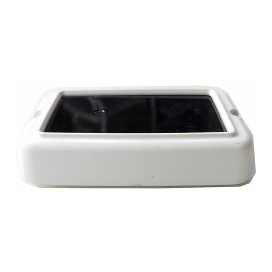
PARTS DESCRIPTION
Mouting hole
Mounting hole
Reflector
Reflector mounting
1
③Examples of connections
●Example 1
When 1 input to plural
sensors are
installed.
1 2 3 4 5
●Example 2
When plural input to plural
sensors are
installed.
1 2 3 4 5
Note 1.
When a magnetic switch or the like is used in the circuit, insert it in
the section
control panel.
2.
The dotted lines indicate connections for additional sensors installed.
④Wiring connections
Remove the terminal cover. Connect the wires with the corresponding
terminals correctly as instructed on the back side of the sensor. Break the
knockouts if necessary.
PR-5B
Case
Operation LED
Lights when an alarm is initiated.
(A red light is seen throngh filter.)
Infrared beam filter
Knockout
Accessory
Double-faced
plate
adhesive sheet
1
2
1 2 3 4 5
Unnecessary when additional
sensors are installed.
1 2 3 4 5
. For more details, refer to instruction manual for
Terminal cover
(Terminals inside)
Sensor mounting
screw (M3×16)
2
Reflector mounting
screw (M4×16)
2
}
+
Power source
−
for sensor
Signal input
Control panel
}
+
Power source
−
for sensor
}
}
Control panel
Advertisement

Related Manuals for Takex PR-5B


Summary of Contents for Takex PR-5B
-
Page 1: Product Description
Please note : This sensor is designed to detect intrusion and to initiate an alarm ; it is not a burglary-preventing device. TAKEX is not responsible for damage, injury or losses caused by accident, theft, Acts of God (including inductive surge by lightning), abuse, misuse, abnormal usage, faulty installation or improper maintenance. -
Page 2: Troubleshooting
(69mm) Limited Warranty TAKEX products are warranted to be free from defects in material and workmanship for 12 months from original date of shipment. Our warranty does not cover damage or failure caused by Acts of God (including inductive surge by lightning), abuse, misuse, abnormal usage, faulty installation, improper maintenance or any repairs other than those provided by TAKEX.
Need help?
Do you have a question about the PR-5B and is the answer not in the manual?
Questions and answers