Advertisement
Quick Links
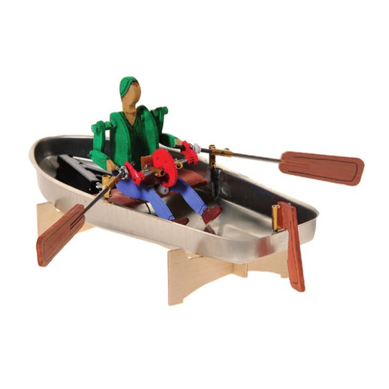
B o a t w i t h m e c h a n i c a l r o w e r
Parts List
Boat hull
Plywood
Welding rod
Black cable
Battery holder
Machine screw
Solarmotor
Electro board
Machine screw
Machine screw
Machine screw
Machine screw
Nuts
Washers
Connection block
Grub screw
Nails
Screw eye
Worm
Double gear ,red
Distance disc, white
E109771#1
109.771
Quantity Size in mm
1
1
300x135x3
2
250x3
1
500
1
2
3x8
1
1
ca. 25x23
2
3x8
2
3x20
2
2x6
4
3x6
12
M3
6
7/3,2
7
2
M3x6
2
20
2
12
1
3
50/10
2
2,9
Part No.
Necessary Tools
1
Pillar drill
2
Machine vice
Wood drills 1 &3mm dia.
3
Metal drill 2mm
4
Screwdriver
5
Fine saw
Soldering iron
6
Metal cutters
7
2 component glue
Wood glue
8
9
10
The OPITEC range of projects is
11
not intended as play toys for
young children.They are tea-
12
ching aids for young people
13
learning the skills of Craft, De-
sign and Technolo- gy.These
14
projects should only be under-
15
16
adult. The finished projects are
17
not suitable to give to children
18
under 3 years old. Some parts
can be swallowed. Dan- ger of
19
20
21
Please Note
taken and tested with the
guidance of a fully qualified
suffocation!
1
Advertisement

Related Manuals for Opitec Hobbyfix


Summary of Contents for Opitec Hobbyfix
- Page 1 Wood glue Electro board ca. 25x23 Machine screw Please Note Machine screw 3x20 The OPITEC range of projects is Machine screw not intended as play toys for young children.They are tea- Machine screw ching aids for young people Nuts learning the skills of Craft, De- sign and Technolo- gy.These...
- Page 2 INSTRUCTIONS Photo 3 Photo 2 Photo 1 1. Mark out on the welding rod (3) the 2. On the second welding rod mark out 2 3. Use a pair of metal bolt cutters to cut following measurements, one piece 2 x 95mm long pieces the welding rod in the marked places x35mm, one piece 1x30mm and one...
- Page 3 INSTRUCTIONS Photo 10 Photo12 Photo 11 11. Drill the centre holes in the 2 connec- 10. Insert a machine screw (6) from the 12. Place a connecter over each of the ters out 3mm diameter. (see photo rear through the 3mm hole in the machine screws as shown.
- Page 4 INSTRUCTIONS Photo 19 Photo 20 19.Saw out the blades for the oars, see patterns Coat the free ends of the wire ( blades 20. Take a connector block and insert a grub screw (16) so that a max of / 95mm ) with 2 component glue and 2mm protrudes ( use instant glue) Screw the free end of the grub screw then mount the blades on the wires in a second connector block so that this can just about turn Diagram 20...
- Page 5 INSTRUCTIONS Photo 29 Photo 31 Photo 30 30. Add a nut (13) and screw it tight 31. Then add another two nuts (13) and assemble the arm (f+g) Leave about a 29. Insert a machine screw 10 space of about 3mm between the first through the hole in part e nut and second pair Photo 33...
- Page 6 INSTRUCTIONS Photo 37 Photo 36 Photo 38 38. Slide the connector block on the 37. The oars go first through the hand ( 36. Glue the rower on the seat as shown so wire for the oars (35mm ) so that the Screw eye ) then in the sawn gear, see that he sits directly on the mechanism handle of the oar cannot slide out of...
- Page 7 Pattern for the rower + wooden parts ø3,0mm Pattern for the stand E109771#1...
- Page 8 E109771#1...
- Page 9 Pattern for the boat hull E109771#1...
- Page 10 E109771#1...
- Page 11 Pattern for the holed board Pattern for the gear Saw roughly to shape first Cutting pattern for the plywood M 1:2 E109771#1...
Need help?
Do you have a question about the Hobbyfix and is the answer not in the manual?
Questions and answers